
Use and Care Manual


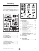


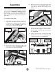
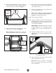

Table Of Contents

-16-
Model T28048 (Mfd. Since 06/17)
3. Attach front frame to table with (3) M5 x 20
tap screws, as shown in Figure 9. Make sure
hook-and-loop material side of frame faces
inward.
4. Prepare (4) frame connector tubes by attach-
ing (8) outer tube clamps to connector tubes
with (8) M6-1 x 50 flat cap head screws
(see Figure 10).
5. Prepare (8) inner tube clamps by inserting
(16) M6-1 hex nuts into accompanying slots
on inner tube clamps (see Figure 10).
Assembly
To assemble router table:
1. Turn router table upside-down on a flat work-
ing surface, then attach (2) side frame sup-
port brackets to table with (4) M5 x 20 tap
screws, as shown in Figure 7. Make sure
hook-and-loop material faces inward.
2. Attach rear frame to table with (3) M5 x 20
tap screws, as shown in Figure 8. Make sure
hook-and-loop material faces inward.
The machine must be fully assembled before it
can be operated. Before beginning the assembly
process, refer to
Needed for Setup
and gather
all
listed items. To ensure the assembly process
goes smoothly, first clean any
parts that are cov-
ered or coated in heavy-duty rust preventative (if
applicable).
Figure 10. Example of a frame connector tube
and inner tube clamps prepared for attachment.
Frame
Connector Tube
Outer
Tube Clamp
Inner
Tube
Clamp
x 16
x 8
Figure 8. Attaching rear frame to table.
Table
Rear
Frame
x 3
Figure 7. Attaching side frame brackets to table.
Side Frame
Bracket
x 4
Hook-and-
Loop Material
Table
Figure 9. Attaching front frame to table.
Front
Frame
Table
x 3
Hook-and-
Loop Material