
Use and Care Manual


Model G1014Z/G1014ZX (Mfd. Since 07/17)
-33-
Horizontal & Edge
Sanding
If the sanding belt frame is in the vertical posi-
tion, proceed to "Setting Up Sander for Horizontal
and Edge Sanding" below to setup the sander
for horizontal sanding. If the sander is already in
the horizontal position, skip ahead to "Performing
Horizontal Sanding and Edge Sanding."
Setting Up Sander for Horizontal
Sanding
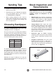
1. Loosen the set screws that secure the work
table support rod to the mounting bracket
behind the motor, then remove the work table
assembly (see Figure 54).
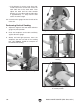
Performing Horizontal or Edge
Sanding
1. Make sure the sanding belt is tensioned —if it
is not already tight.
2. Make sure the belt tracking is correctly set
(see Tracking Belt on Page 40).
3. Turn the sander ON.
2. Loosen the sanding frame rotation lock nuts
(behind the sanding disc cover), rotate the
frame to the horizontal position, as shown in
Figure 55, then tighten the rotation lock nuts.
3. Insert the table support rod into the hole in
the base under the sanding disc, and position
the work table
1
⁄16" away from the sanding
disc, as shown in Figures 32–33 on Page
24.
4. Check that the miter gauge slot-sanding disc
distance is correct (see instructions on Page
49 for further detail).
5. Re-install the backstop so it is square with
and
1
⁄8" above the sanding belt (see Figure
40 on Page 26).
Figure 54. Location for removing work table
assembly.
Set Screws
Figure 55. Table tilted to horizontal position.
Rotation Nut (Hidden)
Sanding Disc
Cover
Rotation Lock
Nut