
Use and Care Manual


Model G1014Z/G1014ZX (Mfd. Since 07/17)
-31-
Table Tilt: Use to tilt the table relative to the
sanding disc or the sanding belt. To tilt the table,
loosen the table tilt lock knob (see Figure 50), tilt
the work table to the desired angle, then retighten
the lock knob.
The work table should be set approximately
1
⁄16"
away from the sanding disc or sanding belt to
prevent fingers or workpieces from getting caught.
To adjust the work table relative to the sanding
disc, refer to Step 16 in Sanding Unit Assembly
on Page 24. To adjust the work table relative to
the belt, refer to Step 9 in Setting up Sander for
Vertical Sanding on Page 37.
Miter Gauge: Use to move workpieces into the
sanding disc (horizontal sanding) or belt (verti-
cal sanding) at a specific angle. To use the miter
gauge (see Figure 50), slide it into the miter slot,
loosen the lock knob, set the angle, then tighten
the knob.
Belt Tracking and Tension: The quick release
tension lever (see Figure 51) tensions the belt. To
tension the sanding belt, move the quick release
tension lever toward the motor.
The tracking control knob keeps the belt in the
center of the idler and drive rollers. To adjust the
belt tracking, loosen the lock nut on the track-
ing control knob. Turn the motor ON, adjust the
tracking in small increments with the knob, then
tighten the lock nut to secure the knob. (Refer to
Tracking Belt on Page 40 for more details.)
Figure 51. Belt tracking and tension controls.
Vertical Tilt and Work Table Position:
The sanding belt frame can be tilted to the vertical
position (see Figure 52) and the work table can
be moved behind the motor to support workpieces
during vertical sanding. (See Vertical Sanding on
Page 36 for more detail.)
Figure 52. Model G1014ZX set up for vertical sanding.
Tracking
Control Knob
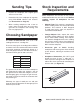
Operation Overview
This combination sander removes surface mate-
rial from the edges, ends, and faces of wood
stock using an abrasive belt and disc. A graphite
coated platen on the sanding belt frame provides
a flat support surface for the sanding belt and
workpiece.
The abrasive belt revolves around a pair of metal
rollers, one of which is driven by the motor. The
adhesive-backed abrasive disc is attached to a
cast iron disc, which revolves in a counterclock-
wise direction.
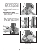
During a typical operation, the sander is turned
ON, and while holding the workpiece with both
hands, the operator gradually eases the workpiece
into the belt or the left side of the sanding disc.
Quick
Release
Tension
Lever
Figure 50. Table tilt controls.
Miter
Gauge
Table Tilt
Lock Knob