
Use and Care Manual


-26-
Model G1014Z/G1014ZX (Mfd. Since 07/17)
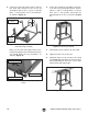
23. Adjust the inside edge of the idler roller guard
1
⁄4-
1
⁄2" away from the sanding belt (see Figure
38).
Figure 38. Correct distance between belt and
idler guard. Measuring distance (inset).
1
⁄4"-
1
⁄2"
24. Rotate the sanding belt just enough to verify
that the belt does not catch on or rub against
the ends of the thumb screws on the sleeve
guard.
25. Tighten the thumb knobs located behind the
idler roller to secure the guard.
28. Loosen the pre-installed
5
⁄16"-18 x 1" hex bolt
and flat washer on the side of the sanding
belt frame, slide the backstop groove onto the
bolt, then finger tighten the bolt.
29. Place a square flat against the sanding belt
and back stop (see Figure 40) adjust the
backstop flush with the square on both sides
of the belt and
1
⁄8" above the belt (see Figure
41), then tighten the hex bolt.
27. At this point, decide if you want to set up the
sanding belt horizontally as in Step 28, or fol-
low the instructions on Page 36 to set up the
sanding belt vertically.
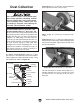
26. G1014ZX Only: Connect the motor cord to
the power cord on the cabinet (see Figure
39). DO NOT connect the sander to the
power until indicated in the Test Run section
on Page 29.
Figure 39. Motor cord connected to power cord.
Power
Cord
Motor
Cord
Figure 40. Adjusting backstop square with belt.
Hex Bolt
Backstop
1
/
8
" Clearance
Platen
Belt
Frame
Backstop
Figure 41. Correct clearance between backstop
and belt.