
Use and Care Manual


Model G1014Z/G1014ZX (Mfd. Since 07/17)
-25-
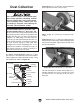
Figure 36. Belt installed onto idler and drive
rollers.
Drive Roller
Idler
Roller
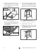
18. Install the 2" dust port onto the back of the
sanding belt frame with the pre-installed
1
⁄4"-
20 x
1
⁄2" hex bolts and flat washers, as shown
in Figure 34.
Figure 34. 2" dust port installed.
19. Assemble the quick release lever, as shown
in Figure 35, using the handle, 6" quick
release lever stud, short lever arm, and
3
⁄8"-16
hex nuts, thread the assembly into the rocker
arm, then tighten the hex nuts.
Figure 35. Quick release lever installed.
Handle
Rocker
Arm
Short
Lever
Arm
6" Stud
Hex Nuts
20. Move the quick release lever toward the
motor, slide the sanding belt over the lever
and onto the idler roller and drive rollers, then
center the belt on the rollers (see Figure 36).
21. Push the lever toward the motor to tension
the sanding belt.
22. Loosen the thumb knobs behind the idler
roller, and install the idler roller assembly
(see Figure 37).
2" Dust
Port
Figure 37. Idler roller guard installed.
Thumb Knob
Idler Roller Guard