
Use and Care Manual


Model G1014Z/G1014ZX (Mfd. Since 07/17)
-23-
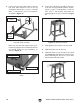
7. While looking through the access hole on the
side of the cover, rotate the plate and tighten
each of the set screws to secure the plate to
the drive shaft (see Figure 27).
9. Install the 2
1
⁄2" black plastic dust port onto the
pulley cover with the (4) #10-24 Phillips head
screws, #10-24 hex nuts and #10 flat wash-
ers, as shown in Figure 29.
Figure 29. 2
1
⁄2" dust port installed.
x4
10. Secure the pulley cover with the thumb knob.
Dust Port
Pulley
Cover
Figure 27. Securing plate to drive shaft.
Set Screws
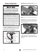
8. Peel off the backing on the 9" PSA (pres-
sure sensitive adhesive) sanding disc, make
sure the cast iron plate is clean, and install
the sanding disc onto the plate, as shown
in Figure 28. Make sure the sanding disc
adheres completely flat against the plate.
Figure 28. Installing sanding disc onto cast iron
plate.
Access Hole
11. Loosen the two set screws on the back of
the base, slide the table support rod into the
shaft, making sure the flat of the shaft faces
the set screws, then tighten the set screws,
as shown in Figure 30. The rod should pro-
trude about 6
1
⁄4" from the side of the base.
Figure 30. Installing table support rod.
6
1
⁄4"
Table
Support
Rod