
Use and Care Manual


-22-
Model G1014Z/G1014ZX (Mfd. Since 07/17)
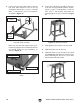
3. Slide the flat ends of the idler roller into
the slots on the roller adjustment bars (see
Figure 23).
Figure 23. Idler roller installed.
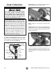
4. Use the 4mm hex wrench to back the shaft
set screws on the cast iron plate out of the
shaft hole and keyway (see Figure 24).
Figure 24. Set screw locations on sanding disc
plate.
Set Screws
6. Adjust the cast iron plate so it protrudes
slightly (
1
⁄16"-
1
⁄8") beyond the curved lip of
the metal cover on both sides, as illustrated
in Figure 26, to avoid the possibility of
workpieces hitting the cover during sanding
operations.
Plate
Lip
Cover
1
/
16
"-
1
/
8
"
(Top View)
Figure 26. Gap between plate and cover.
5. Align the keyway on the plate with the drive
shaft key, then slide the plate onto the shaft,
as shown in Figure 25.
Figure 25. Installing plate onto drive shaft.
Key
Idler Roller
Figure 22. G1014ZX sander fastened to cabinet
(two of four hex bolts shown).
x 4