MODEL G1014Z/G1014ZX 6" X 48" BELT/9" DISC COMBINATION SANDER OWNER'S MANUAL (For models manufactured since 07/17) G1014Z G1014ZX COPYRIGHT © MARCH, 2009 BY GRIZZLY INDUSTRIAL, INC., REVISED APRIL, 2019 (MN) WARNING: NO PORTION OF THIS MANUAL MAY BE REPRODUCED IN ANY SHAPE OR FORM WITHOUT THE WRITTEN APPROVAL OF GRIZZLY INDUSTRIAL, INC. #BL11448 PRINTED IN TAIWAN V2.04.
This manual provides critical safety instructions on the proper setup, operation, maintenance, and service of this machine/tool. Save this document, refer to it often, and use it to instruct other operators. Failure to read, understand and follow the instructions in this manual may result in fire or serious personal injury—including amputation, electrocution, or death. The owner of this machine/tool is solely responsible for its safe use.
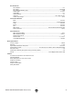
Table of Contents INTRODUCTION................................................ 2 Contact Info.................................................... 2 Machine Description....................................... 2 Manual Accuracy............................................ 2 Identification.................................................... 3 G1014Z Machine Data Sheet......................... 4 G1014ZX Machine Data Sheet....................... 6 SECTION 1: SAFETY........................................
INTRODUCTION Contact Info Manual Accuracy We stand behind our machines! If you have questions or need help, contact us with the information below. Before contacting, make sure you get the serial number and manufacture date from the machine ID label. This will help us help you faster. We are proud to provide a high-quality owner’s manual with your new machine! Grizzly Technical Support 1815 W. Battlefield Springfield, MO 65807 Phone: (570) 546-9663 Email: techsupport@grizzly.
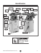
Identification 9" Sanding Disc 2" Dust Port Idler Roller Guard Idler Roller Platen Work Table Miter Gauge Back Stop Tracking Knob Drive Roller Sanding Belt Pulley Cover Angle Scale 21⁄2" Dust Port Angle Scale Lock Knob Support Rod Quick Release Tension Lever ON/OFF Switch w/ Disabling Key Door Handle Cabinet Power Cord Foot Figure 1. G1014ZX identification. To reduce your risk of serious injury, read this entire manual BEFORE using machine. Model G1014Z/G1014ZX (Mfd.
MACHINE DATA SHEET Customer Service #: (570) 546-9663 · To Order Call: (800) 523-4777 · Fax #: (800) 438-5901 MODEL G1014Z COMBINATION SANDER 6" X 48" BELT 9" DISC Z SERIES Product Dimensions: Weight.............................................................................................................................................................. 117 lbs. Width (side-to-side) x Depth (front-to-back) x Height...........................................................................
Disc Sander Info Disc Diameter.............................................................................................................................................. 9 in. Disc Speed........................................................................................................................................ 3450 RPM Disc Sandpaper Backing Type.................................................................................................................... PSA Table Length.................
MACHINE DATA SHEET Customer Service #: (570) 546-9663 · To Order Call: (800) 523-4777 · Fax #: (800) 438-5901 MODEL G1014ZX COMBINATION SANDER WITH CABINET STAND Product Dimensions: Weight.............................................................................................................................................................. 148 lbs. Width (side-to-side) x Depth (front-to-back) x Height........................................................................... 30 x 24 x 56 in.
Main Specifications: Belt Sander Info Sanding Belt Width...................................................................................................................................... 6 in. Sanding Belt Length.................................................................................................................................. 48 in. Sanding Belt Speed...........................................................................................................................
SECTION 1: SAFETY For Your Own Safety, Read Instruction Manual Before Operating This Machine The purpose of safety symbols is to attract your attention to possible hazardous conditions. This manual uses a series of symbols and signal words intended to convey the level of importance of the safety messages. The progression of symbols is described below. Remember that safety messages by themselves do not eliminate danger and are not a substitute for proper accident prevention measures.
WEARING PROPER APPAREL. Do not wear clothing, apparel or jewelry that can become entangled in moving parts. Always tie back or cover long hair. Wear non-slip footwear to reduce risk of slipping and losing control or accidentally contacting cutting tool or moving parts. HAZARDOUS DUST. Dust created by machinery operations may cause cancer, birth defects, or long-term respiratory damage. Be aware of dust hazards associated with each workpiece material.
Additional Safety for Belt & Disc Sanders Serious injury or death can occur from fingers, clothing, jewelry, or hair getting entangled in rotating disc, belt, spindle or other moving components. Abrasion injuries can occur from touching moving sandpaper with bare skin. Workpieces thrown by sanding surface can strike operator or bystanders with moderate force, causing impact injuries. Long-term respiratory damage can occur from using sander without proper use of a respirator.
SECTION 2: POWER SUPPLY Availability Circuit Information Before installing the machine, consider the availability and proximity of the required power supply circuit. If an existing circuit does not meet the requirements for this machine, a new circuit must be installed. To minimize the risk of electrocution, fire, or equipment damage, installation work and electrical wiring must be done by an electrician or qualified service personnel in accordance with all applicable codes and standards.
Grounding Requirements This machine MUST be grounded. In the event of certain malfunctions or breakdowns, grounding reduces the risk of electric shock by providing a path of least resistance for electric current. For 110V operation: This machine is equipped with a power cord that has an equipment-grounding wire and a grounding plug (see following figure).
SECTION 3: SETUP Needed for Setup This machine presents serious injury hazards to untrained users. Read through this entire manual to become familiar with the controls and operations before starting the machine! Wear safety glasses during the entire setup process! This machine and its components are very heavy. Get lifting help or use power lifting equipment such as a forklift to move heavy items. Like all machinery there is potential danger when operating this machine.
Hardware Recognition Chart 5mm -14- Model G1014Z/G1014ZX (Mfd.
G1014Z Inventory A The following is a list of items shipped with your machine. Before beginning setup, lay these items out and inventory them. If any non-proprietary parts are missing (e.g. a nut or a washer), we will gladly replace them; or for the sake of expediency, replacements can be obtained at your local hardware store. Box 1 (Figures 4–6) Qty A. Sander Unit.................................................. 1 B. Stand Legs................................................... 4 C. Long Lower Braces...
G1014ZX Inventory A The following is a list of items shipped with your machine. Before beginning setup, lay these items out and inventory them. If any non-proprietary parts are missing (e.g. a nut or a washer), we will gladly replace them; or for the sake of expediency, replacements can be obtained at your local hardware store. Box 1 (Figures 7–8) Qty A. Sander Unit.................................................. 1 B. Sanding Belt 6" x 48"................................... 1 C. Dust Port 21⁄ 2" (Black).
Cleanup The unpainted surfaces of your machine are coated with a heavy-duty rust preventative that prevents corrosion during shipment and storage. This rust preventative works extremely well, but it will take a little time to clean. Be patient and do a thorough job cleaning your machine. The time you spend doing this now will give you a better appreciation for the proper care of your machine's unpainted surfaces.
Mounting to Shop Floor Although not required, we recommend that you mount your new Model G1014Z sander to the floor. The Model G1014ZX sander cabinet cannot be mounted to the floor because the mounting holes cannot be accessed through the cabinet. However, you can use machine mounts on the G1014ZX cabinet. Because this is an optional step and floor materials may vary, floor mounting hardware is not included. Generally, you can either bolt your machine to the floor or mount it on machine mounts.
G1014Z Stand Assembly 3. The Model G1014Z stand can be assembled with the included feet or mounted directly to a concrete floor (refer to Mounting to Shop Floor on Page 18 for further details). Note: Make sure the lip on the long braces faces up. To assemble the G1014Z Stand: 1. Fasten a long upper and long lower brace to the two stand legs with (8) 5⁄16"-18 x 1⁄2" carriage bolts, 5⁄16"-18 hex nuts, and 5⁄16" flat washers, as shown in Figure 14. Finger tighten the fasteners for now.
5. Fasten the two short upper braces and the two short lower braces to one of the leg assemblies with the (8) 5⁄16"-18 x 1⁄2" carriage bolts, 5⁄16"-18 hex nuts, and 5⁄16" flat washers, as shown in Figure 15. 6. Fasten the second leg assembly to the braces on the first leg assembly with the remaining (8) 5⁄16"-18 x 1⁄2" carriage bolts, 5⁄16"-18 hex nuts, and 5⁄16" flat washers, then place the stand upright on its feet, as shown in Figure 17. Short Lower Brace x8 Short Upper Braces Figure 15.
G1014ZX Cabinet Assembly Sanding Unit Assembly To assemble the G1014ZX cabinet: To assemble the sanding unit: 1. Place the stand flat on its side, but do not lay it down on the switch or door handle. 1. 2. Insert a 5⁄16"-18 x 1" hex bolt through the bottom of each of the four rubber feet, then insert the hex bolt on each foot into the mounting holes on the bottom of the cabinet. 3.
4. Use the 4mm hex wrench to back the shaft set screws on the cast iron plate out of the shaft hole and keyway (see Figure 24). x4 Set Screws Figure 22. G1014ZX sander fastened to cabinet (two of four hex bolts shown). 3. Slide the flat ends of the idler roller into the slots on the roller adjustment bars (see Figure 23). Figure 24. Set screw locations on sanding disc plate. 5. Align the keyway on the plate with the drive shaft key, then slide the plate onto the shaft, as shown in Figure 25.
7. While looking through the access hole on the side of the cover, rotate the plate and tighten each of the set screws to secure the plate to the drive shaft (see Figure 27). 9. Install the 21⁄2" black plastic dust port onto the pulley cover with the (4) #10-24 Phillips head screws, #10-24 hex nuts and #10 flat washers, as shown in Figure 29. Set Screws x4 Access Hole Figure 27. Securing plate to drive shaft. 8.
12. Loosen the two set screws on the work table arm so their ends are flush with the inside of the opening, as shown in Figure 31. Opening Work Table Arm 15. Using a ruler adjust the edge of the work table approximately 1⁄16" away from the sanding disc on both sides (see Figure 33), then tighten the set screws on the work table arm. Set Screws Angle Adjustment Knob ⁄16" Gap 1 Table Mount Bracket Screw Figure 31. Location of set screws on work table arm. 13.
18. Install the 2" dust port onto the back of the sanding belt frame with the pre-installed 1⁄4"20 x 1⁄2" hex bolts and flat washers, as shown in Figure 34. 2" Dust Port 20. Move the quick release lever toward the motor, slide the sanding belt over the lever and onto the idler roller and drive rollers, then center the belt on the rollers (see Figure 36). Idler Roller Drive Roller Figure 34. 2" dust port installed. 19.
23. Adjust the inside edge of the idler roller guard 1 1 ⁄4- ⁄2" away from the sanding belt (see Figure 38). 27. At this point, decide if you want to set up the sanding belt horizontally as in Step 28, or follow the instructions on Page 36 to set up the sanding belt vertically. 28. Loosen the pre-installed 5⁄16"-18 x 1" hex bolt and flat washer on the side of the sanding belt frame, slide the backstop groove onto the bolt, then finger tighten the bolt. ⁄4"-1⁄2" 1 Figure 38.
Calibrating Miter Gauge The miter gauge needs to be calibrated to the sanding disc when it is first mounted in the miter slot. Pre-Tracking Belt You must perform the following procedure before the test run to ensure that the belt does not come off or get jammed against the sanding belt frame. To pre-track the belt: To calibrate the miter gauge: 1. DISCONNECT SANDER FROM POWER! 1. 2.
Dust Collection Figure 45 shows a 2" dust hose connected to the dust collection port with a hose clamp. This machine creates a lot of wood chips/ dust during operation. Breathing airborne dust on a regular basis can result in permanent respiratory illness. Reduce your risk by wearing a respirator and capturing the dust with a dust-collection system. Recommended CFM at 2" Dust Port: 100 Recommended CFM at 21 ⁄ 2" Dust Port: 150 Do not confuse this CFM recommendation with the rating of the dust collector.
Test Run Test run your machine to make sure it runs properly and is ready for regular operation. The test run consists of verifying the following: 1) The motor powers up and runs correctly, and 2) the safety disabling mechanism on the switch works correctly. You must perform the pre-tracking procedure on Page 27 before starting the sander to ensure that the belt does not come off of the rollers or jam against the sander during startup.
SECTION 4: OPERATIONS Basic Controls To reduce your risk of serious injury, read this entire manual BEFORE using machine. Eye injuries, respiratory problems, or hearing loss can occur while operating this tool. Wear personal protective equipment to reduce your risk from these hazards. Keep hair, clothing, and jewelry away from moving parts at all times.
Table Tilt: Use to tilt the table relative to the sanding disc or the sanding belt. To tilt the table, loosen the table tilt lock knob (see Figure 50), tilt the work table to the desired angle, then retighten the lock knob. The work table should be set approximately 1⁄ 16" away from the sanding disc or sanding belt to prevent fingers or workpieces from getting caught. To adjust the work table relative to the sanding disc, refer to Step 16 in Sanding Unit Assembly on Page 24.
Sanding Tips • Replace the sandpaper with a higher grit to achieve a finer finish. Stock Inspection and Requirements Some workpieces are not safe or may require modification before they are safe to sand. Before sanding, inspect all workpieces for the following: • Extend the life of the sandpaper by regularly using PRO-STIK® abrasive belt cleaners (see Accessories on Page 41).
Horizontal & Edge Sanding 2. If the sanding belt frame is in the vertical position, proceed to "Setting Up Sander for Horizontal and Edge Sanding" below to setup the sander for horizontal sanding. If the sander is already in the horizontal position, skip ahead to "Performing Horizontal Sanding and Edge Sanding." Loosen the sanding frame rotation lock nuts (behind the sanding disc cover), rotate the frame to the horizontal position, as shown in Figure 55, then tighten the rotation lock nuts.
4. While holding the back end of the workpiece against the backstop with both hands, and while keeping your fingers away from the belt, slowly feed the workpiece into the belt, as shown in Figures 56 & 57. Note: Apply even pressure and move the workpiece back and forth across the sanding belt. Contour Sanding To perform contour sanding: 1. Make sure the sanding belt is tensioned—if it is not already tight. 2. Make sure the belt tracking is correctly set (see Tracking Belt on Page 40). 3.
Disc Sanding The sanding disc can be used to smooth the ends of workpieces. To reduce the risk of your fingers getting trapped between the work table and sanding disc, make sure the table is approximately 1 ⁄ 16" away from the sanding disc. Figure 60. Example of miter sanding. Always keep the workpiece on the left side of the wheel that rotates down toward the work table. This will keep the workpiece from flying out of your hands due to kickback. To use the sanding disc: 1.
Vertical Sanding 6. If the sanding belt frame is in the horizontal position, proceed to Setting up Sander for Vertical Sanding. If the sander is already in the vertical position, skip to Performing Vertical Sanding on Page 38. Raise the sanding belt frame until it reaches the 90º mark (or the desired angle) on the tilt scale, as shown in Figure 65, then tighten the rotation lock nuts. Setting up Sander for Vertical Sanding 1. Make sure the sanding belt is tensioned—if it is not already tight. 2.
9. Adjust the front of the work table 1⁄16" away from the sanding belt (see Figure 67) across its entire length. 11. Place a machinist's square on the work table and against the sanding belt, as shown in Figure 69, and check for gaps between the square, belt, and table. ⁄16" Gap 1 Figure 67. Correct distance between work table and sanding belt.
—If the distance is not the same from sideto-side, loosen the screws that secure the work table arm to the work table. Then adjust the table until the miter slot-belt distance is even side-to-side and the table is approximately 1⁄16" away from the belt across its entire length. 13. Insert the miter gauge into the left side of the miter slot. Performing Vertical Sanding 1. Adjust the angles of the work table and miter gauge for your operation. 2.
Changing Sanding Belt 6. Position the belt in the center of the roller, then move the quick release tension lever toward the motor to tension the belt (see Figure 76). Some sanding belts are designed to sand in only one direction and will have a direction indicated on the back of the belt. The Model G1014Z/ G1014ZX is designed so that the sanding belt travels clockwise as viewed from the side with the quick release tension lever. To change the sanding belt: 1. DISCONNECT SANDER FROM POWER! 2.
Tracking Belt The aim of tracking the belt is to keep it centered on the rollers. To track the belt: Changing Sanding Disc The model G1014Z/G1014ZX accepts 9" diameter paper-backed pressure sensitive adhesive (PSA) discs (refer to Accessories on Page 41). 1. Make sure the belt is properly pre-tracked (refer to Pre-Tracking Belt on Page 27). 2. Tie back loose clothing and long hair to protect yourself from getting caught in the moving sanding belt when you start the machine. 1.
Accessories SECTION 5: ACCESSORIES Installing unapproved accessories may cause machine to malfunction, resulting in serious personal injury or machine damage. To reduce this risk, only install accessories recommended for this machine by Grizzly. NOTICE Refer to our website or latest catalog for additional recommended accessories. 9" PSA Aluminum Oxide Sanding Discs Our aluminum oxide sanding discs are manufactured in ISO 9002 factories to ensure the highest quality and are available in packs of two.
SECTION 6: MAINTENANCE To reduce risk of shock or accidental startup, always disconnect machine from power before adjustments, maintenance, or service. Schedule For optimum performance from this machine, this maintenance schedule must be strictly followed. Ongoing Loose mounting bolts. • • Worn or damaged sanding belt or disc. • Worn or damaged wires. • Wipe the work table clean after every use— this ensures moisture from wood dust does not remain on bare metal surfaces. • Worn or damaged wires.
Table Support Rod Rocker Plate Oil Type...................T23962 or ISO 68 Equivalent Oil Amount..............................................Thin Coat Lubrication Frequency..............................Annually Oil Type........................................ NLGI#2 Grease Oil Amount................................................... Dollop Lubrication Frequency..............................
SECTION 7: SERVICE Review the troubleshooting procedures in this section if a problem develops with your machine. If you need replacement parts or additional help with a procedure, call our Technical Support. Note: Please gather the serial number and manufacture date of your machine before calling. Troubleshooting Motor & Electrical Symptom Possible Cause Possible Solution Machine does not start or a breaker trips. 1. Switch disabling key removed. 2.
Machine Operation Symptom Possible Cause Possible Solution Machine vibrates 1. Sander not secured properly to stand 1. Tighten fasteners that mount sander to stand excessively. (G1014Z) or cabinet (G1014ZX). (G1014Z) or cabinet (G1014ZX). 2. Secure stand to floor, reposition to level surface, or 2. Stand not stable on floor. shim stand. 3. Check/adjust motor mounting. 3. Incorrect motor mounting. 4. Adjust idler roller. 4. Idler roller is too loose. 5. Replace sanding belt (see Page 39). 5.
V-Belt Tension & Replacement The V-belt is pre-installed and tensioned at the factory. However, we recommend you verify this setting and also check the V-belt tension after the first 16 hours of operation, during which the belt will stretch and seat. —If there is approximately 1⁄4" deflection, no adjustments are necessary. Go to Step 9. —If there is more or less than that 1⁄4" deflection when you push the V-belt with moderate pressure, follow Steps 6-7. 6. Tools Needed Qty Hex Wrench 4mm..................
Replacing V-Belt 1. DISCONNECT SANDER FROM POWER! 2. Follow Steps 2-4 in Tensioning V-Belt on Page 46. 3. Loosen the four hex bolts that secure the motor to the base, as shown in Figures 85–86, then slide the motor toward the back of the sander to reduce belt tension. 4. Remove the V-belt and replace it with a new one. 5. Slide the motor toward the front of the sander, then tighten the four hex bolts on the motor base. 6. 7. Repeat Step 5 on Page 46 and adjust the V-belt tension as needed.
Pulley Alignment Proper pulley alignment prevents premature belt wear. The pulleys are properly aligned when they are parallel and in the same plane as each other. Tools Needed Qty Hex Wrench 4mm................................................ 1 Straightedge 12".................................................. 1 Standard Screwdriver.......................................... 1 To check and adjust pulley alignment: 6.
Miter Slot-Disc Parallelism 3. —If the distance is the same, no adjustments need to be made. If the miter slot is not parallel with the disc, workpieces may not be sanded correctly when using the miter gauge. —If the distance is not the same from side to side, loosen the screws (see Figure 68 on Page 37) that secure the work table arm to the work table and adjust the table so it is approximately 1⁄16" away from the sanding belt across its entire length. Tools Needed Qty Combination Square.............
SECTION 8: WIRING These pages are current at the time of printing. However, in the spirit of improvement, we may make changes to the electrical systems of future machines. Compare the manufacture date of your machine to the one stated in this manual, and study this section carefully. If there are differences between your machine and what is shown in this section, call Technical Support at (570) 546-9663 for assistance BEFORE making any changes to the wiring on your machine.
G1014Z Wiring Diagram Start Capacitor 200MFD 125VAC MOTOR (Prewired 110V) Ground Figure 92. G1014Z 110V motor wiring. MOTOR (Wired 220V) Start Capacitor 200MFD 125VAC PADDLE SWITCH (viewed from behind) Ground (Wired 220V) Ground 5-15 PLUG (Included) 110V (Wired 220V) Neutral Figure 93. G1014Z switch wiring. Hot Ground Hot G 220V Hot 6-15 PLUG (As Recommended) Model G1014Z/G1014ZX (Mfd.
G1014ZX Wiring Diagram Start Capacitor 200MFD 125VAC MOTOR (Prewired 110V) Ground Figure 94 G1014ZX motor wiring. MOTOR (Wired 220V) Start Capacitor 200MFD 125VAC PADDLE SWITCH (viewed from behind) Ground (Wired 220V) Ground 5-15 PLUG (Included) 110V Figure 95. G1014ZX switch wiring. (Wired 220V) Neutral Hot Ground G Hot 220V Hot 6-15 PLUG (As Recommended) -52- READ ELECTRICAL SAFETY ON PAGE 50! Model G1014Z/G1014ZX (Mfd.
SECTION 9: PARTS We do our best to stock replacement parts when possible, but we cannot guarantee that all parts shown are available for purchase. Call (800) 523-4777 or visit www.grizzly.com/parts to check for availability.
G1014Z Main Parts List REF PART # DESCRIPTION REF PART # DESCRIPTION 1 2 3 4 5 6 7 8 9 10 11 12 13 14 15 16A 17 18 19 20 21 22 23 24 25 26 27 27A 28 29 30 32 33 34 35 36 37 39 40 41 42 43 43-1 43-2 43-3 43-4 43-5 43-6 44 45 46 49 P1014Z001 P1014Z002 P1014Z003 P1014Z004 P1014Z005 P1014Z006 P1014Z007 P1014Z008 P1014Z009 P1014Z010 P1014Z011 P1014Z012 P1014Z013 P1014Z014 P1014Z015 P1014Z016A P1014Z017 P1014Z018 P1014Z019 P1014Z020 P1014Z021 P1014Z022 P1014Z023 P1014Z024 P1014Z025 P1014Z026 P1014Z027 P101
G1014Z Stand 109A 113 32 13 112 12 13 12 65 109 12 13 13 REF PART # DESCRIPTION 12 13 32 41 58 65 109 109A 110 111 112 113 HEX NUT 5/16-18 FLAT WASHER 5/16 HEX BOLT 5/16-18 X 1/2 HEX BOLT 5/16-18 X 1 RUBBER FOOT CARRIAGE BOLT 5/16-18 X 5/8 LEG STAND ASSEMBLY LOWER BRACE (LONG) LOWER BRACE (SHORT) UPPER BRACE (LONG) UPPER BRACE (SHORT) P1014Z012 P1014Z013 P1014Z032 P1014Z041 P1014Z058 P1014Z065 P1014Z109 P1014Z109A P1014Z110 P1014Z111 P1014Z112 P1014Z113 110 111 65 58 41 G1014Z Labels & Cos
G1014ZX Main 5 100 107 108 96 14 26 30 4 32 13 97 10 29 25 33 11 17 24 7 15 7 17 103 95 70 12 98 13 94 39 77 27 26 25 33 23 19 97 32 28 42 21 35 6 18 93 34 40 115 22 128 42 80 51 97 36 116 115 62 3 2 116 81 106 105 82 106 87 89 84 43 120 92 41 91 46 9 102 83 119 10 99 85 1 8 41 13 86 37 3 2 64 59 3 101 2 89 114A 88 10 114A-1 127 126 96 57 56 16A 52 44 45 43-3 69 43-5 27 28 43-2 43-6 117 43-1 12 43-4 20 -56- BUY PARTS ONLINE AT GRIZZLY.
G1014ZX Main Parts List REF PART # DESCRIPTION REF PART # DESCRIPTION 1 2 3 4 5 6 7 8 9 10 11 12 13 14 15 16A 17 18 19 20 21 22 23 24 25 26 27 28 29 30 32 33 34 35 36 37 39 40 41 42 43 43-1 43-2 43-3 43-4 43-5 43-6 44 45 DUST COVER EXT RETAINING RING 12MM BALL BEARING 6201-2RS DRIVER ROLLER SHAFT SANDING BELT 6'' X 48'' KEY 5 X 5 X 40 EXT RETAINING RING 15MM SANDING BELT FRAME BACK STOP SET SCREW 5/16-18 X 3/8 DRIVE ROLLER HEX NUT 5/16-18 FLAT WASHER 5/16 KNOB BALL BEARING 6202-2RS W/SNAP RING COMPLET
G1014ZX Cabinet REF PART # DESCRIPTION REF PART # DESCRIPTION 12 13 32 41 46 47 48 49 51 53 55 HEX NUT 5/16-18 FLAT WASHER 5/16 HEX BOLT 5/16-18 X 1/2 HEX BOLT 5/16-18 X 1 FLAT WASHER #10 FLANGE SCREW 10-24 X 3/8 EXT TOOTH WASHER #10 STRAIN RELIEF HEX NUT 10-24 GRIZZLY SAFETY PADDLE SWITCH PADDLE SWITCH KEY 58 71 72 72-1 73 73A 74 75 76 78 118 RUBBER FOOT POWER CORD MOTOR CORD 1 FEMALE MOTOR CORD 2 MALE CABINET COMPLETE STAND ASSY BOX 2 CABINET DOOR DOOR LATCH SYSTEM SHELF SWITCH HOUSING TAP SCREW #
G1014ZX Labels & Cosmetics 129 133 131 WARNING! ABRASION INJURY HAZARD! 66 DO NOT place hands on or near sanding belt while it is moving. Serious injuries may occur! INJURY/SHOCK 104 HAZARD! Disconnect power before adjustments, maintenance, or service. 67 WARNING! To reduce risk of death or serious injury, read manual BEFORE using machine. To get a new manual, call (800) 523-4777 or go to www.grizzly.com.
FOLD ALONG DOTTED LINE Place Stamp Here GRIZZLY INDUSTRIAL, INC. P.O.
WARRANTY & RETURNS Grizzly Industrial, Inc. warrants every product it sells for a period of 1 year to the original purchaser from the date of purchase. This warranty does not apply to defects due directly or indirectly to misuse, abuse, negligence, accidents, repairs or alterations or lack of maintenance.