
User Manual

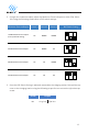

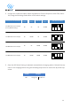
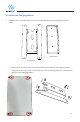

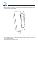

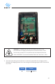
Table Of Contents
- 1. Introduction & Unpacking
- 2. Installation Planning and Service Wiring:
- 3. Adjustable Maximum Current Output
- 4. Installation
- 5. Wiring Connection
- 6. EasyEvPlug Holster and Cable Management System
- 7. Charging Status Indicators and Buzzers
- 8. Operation
- 9. General Product Care and Use Information
- 10. Warranty and Return Policy

19
5. Wiring Connection
5.1 Optional Hardwire Connection
1. Choose the appropriate conduit in accordance with all applicable, local, and electrical
safety codes and standards.
2. Using the appropriate tool, clamp the ring wire terminal to the copper wire. For non-
insulated terminals, use heat shrink tube to cover the non-insulated portion of the
terminal. Choose a terminal ring with the following characteristics:
» Recommended Wire Strip length: 8mm (0.32in)
» Width of the terminal block opening: 10.2mm (0.41in)
3. Remove the front cover by removing the 4 screws at each corner of the charging station.
For more information on how to remove the front cover refer to Chapter 3.1 Adjust
Maximum Current Output on page 10.
4. With the front cover placed to the side, use Philips screwdriver to release terminal screws
of the input cable. Loosen the Strain Relief Fitting for the 6-50 or 14-50 Plug and Remove
the Plug. Remove the Strain Relief connector.
5. Insert the wire end passing through the conduit and insert them into the input wiring
hole. (Use Red wire for L1, Black wire for L2, Green wire for G). Attach the terminal to the
corresponding terminal block. Use the following wire and torque force when connecting to
input terminal block.
Terminal Conductor
Screw Rating Torque
90C,
copper wire
M4
L1, L2, G
8 AWG
(10AWG for ground)
max 1.8Nm | 16 LBF.IN