Crathco® Post Mix Beverage Dispensers Operation and Instruction Manual for Model PM4-B & PM45-B TABLE OF CONTENTS Warnings and Safety Precautions..................2 Installation ..................................................3-5 Operating and Adjustments.........................5-7 Care and Cleaning......................................7-9 Maintenance Service ................................9-10 Troubleshooting.......................................11-16 Exploded Views ..................................
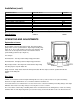
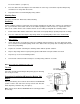
WARNING LABELS AND SAFETY PRECAUTIONS OPERATOR'S SAFETY PRECAUTIONS 1. 2. 3. Read and understand the operating instructions in this manual thoroughly. Note all warning labels. If any of the warning labels are missing or damaged replace them immediately. Keep operating area clean. Located on the top of the condenser shroud and on the rear panel. INTRODUCTION The GRINDMASTER CORPORATION dispenser is a unique, self contained, counter top style unit with high capacity self-adjusting cooling systems.
INSTALLATION Installation Notice A water filter is recommended for the water supply to the dispenser, especially in areas where water contains a high level of minerals such as calcium or other solids. Over long periods of time, calcium deposits build on heat-exchanger coils and will lower the cooling capacity of the system. Calcium build up will also occur on the strainers enclosed in the dispensing valves. The cooling system is provided with copper coils, designed to last the life of the dispenser.
WARNING: Only a qualified service technician should service internal electrical components. Installing Your Unit (cont.) 4. Water Hook-up. It is recommended to provide water connection to the dispenser from a dedicated water line.
Installation (cont.) POWER SUPPLY: COMPRESSOR: REFRIGERANT: DESIGN LOW PRESSURE: DESIGN HIGH PRESSURE: SYSTEM TYPE: IDLE POWER CONSUMPTION RUN POWER CONSUMPTION FUSE SIZE DISPENSING RATIO SUPPLY WATER PRESSURE WORKING AMBIENT TEMPERATURE PRODUCT STORAGE CAPACITY Specifications: 220 VAC 50 Hz 115/60Hz HP: 1/4, (630 Kcal, 2500 BTUH) R134a 260 grams/9.1 oz. Max. 9.5 BAR; 140 PSIG Max. 16.3 BAR; 240 PSIG CAPILLARY TUBE, HERMETIC .5A .8A 4A, 5A (MAX) 7A, 8A (MAX) 6 A Slow Blow Controller 50 ML/SEC 2 - 2.
correct value with the use of a refractometer. Setting brix by taste is an acceptable method and usually gives + 0.5-0.8 brix error. Brix Setup (cont.) Mixing water with a concentrate in this dispenser was designed at the following conditions: 1. The initial temperature of a concentrate (syrup) used in the dispenser should be 39-41ÞF (4-5°C). 2. The initial temperature of the water supplied by the dispenser cooling system is 39ÞF (4°C). 3. The static water pressure should be set to 29PSIG.
Once the brix is set, use the same flavor set up on each dispensing head. The flavor used on a particular dispensing head can be changed if the brix and viscosity of the syrup remains the same. Dispenser Operation Tips 1. To dispense the drink, depress and hold dispensing push button as long as needed. 2. After dispensing 2 liters consecutively allow a 15-30 second idling time before next usage. 3. Keep dispenser door closed and do not allow it to be open for a longer time than necessary. 4.
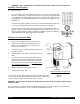
Washing Parts (cont.) Remove the dispensing nozzle from the machine by turning it 90° to the left or right side, pulling it down. If there is a problem pulling it down, turn the nozzle with quick short left to right and back motions pulling it down at the same time. Make sure that the nozzle is in the proper position. The flat part of the thin round plate should be between screw heads. Remove product pick up tubes from the product containers. ---- 2. Note: Static mixer is inside the nozzle.
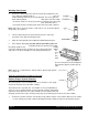
into clean container. (see figure H) 2. Close the cabinet door and dispense the warm water the same way, as it would be a product. Dispensing should last for no longer than 90 seconds. 3. Repeat the above for all remaining dispensing stations. Washing Parts Proceed as described in “Wash Parts” without flushing. Sanitizing Prepare sanitizing solution per instruction on the package changing the strength of the solution to be equivalent to 6+1 e.g.
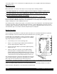
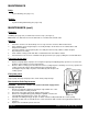
MAINTENANCE Daily: System Flushing (See pages 7-8) Weekly: System flushing and washing (See pages 8-9) MAINTENANCE (cont.) Biweekly: Sanitizing (See page 8-9). Ice bank water level check up. (See figure J) Note: Make sure that water level in the drain tube is even with tank overflow outlet. Monthly: 1. 2. 3. 4. 5. Check the condenser for dust build up. If necessary clean the condenser with a bristle brush.
TROUBLESHOOTING WARNING: Only a qualified service technician should perform Electrical and mechanical adjustments of repairs. Always disconnect power before attempting any maintenance procedures.
TROUBLESHOOTING (con’t.
TROUBLESHOOTING (con’t.
TROUBLESHOOTING (con’t.) 1. THERE IS RESTRICTION IN WATER SUPPLY LINE OR IN THE COOLING COIL 2.
TROUBLESHOOTING (con’t.) UNIT DISPENSES POOR BRIX DRINK OR SYRUP/CONCENTRATE ONLY UNIT DISPENSES SYRUP/CONCENTRATE ONLY IS DRINK TOO RICH 1. CHECK CORRESPONDING SOLENOID VALVE FOR POWER SUPPLY OR MALFUNCTION 2.
TROUBLESHOOTING (con’t.
FINAL ASSEMBLY EXPLODED ITEM P/N DESCRIPTION 1 2 3 4 5 6 7 8 9 10 11 12 13 14 15 16 17 18 19 20 3373 9105 9108 9137 0069 9110 9126 9304 9307 9308 9311 9315 9316 9319 9322 9803 9811 9814 9193 9213 9233 9214 9204 0073 SWITCH, ROCKER O-RING, .864 ID X .
CONDENSING UNIT EXPLODED VIEW ITEM 1 2 3 4 5 6 7 8 9 10 11 12 13 14 15 16 17 P/N 1828 1830 1831 9506 9517 9532 3250 3247 3371 9521 8218 9522 9205 1000 1459 1584 1336 0055 9702 0057 3370 DESCRIPTION GROMET, COMPRESSOR 3250 WASHER, COMPRESSOR CLIP, COMPRESSOR VALVE, INLET 2.
DISPENSING BASE EXPLODED VIEW REPLACEMENT PUMP KITS MAY BE ORDERED AS FOLLOWS: P/N 9400 ITEM 6 7 8 11 12 13 17 ITEM 1 2 3 4 5 6 7 8 9 10 11 12 13 14 15 16 17 18 P/N 9103 9123 9124 9132 9133 9134 9135 9136 9137 9141 9160 9161 9162 9163 9164 0069 9177 9212 DESCRIPTION FITTING, ELBOW 45 1/4 X BARB FITTING, ELBOW 45 3/8 X BARB DOUBLE O’ RING FITTING, Y BARB X 1/4 ID GEAR MOTOR, SHORT SHAFT 24V DC NOM GEAR MOTOR, LONG SHAFT 24V DC NOM ROLLER ASSY, SYRUP, PERISTALTIC PUMP COVER, ANKO PERIST, PUMP 810 HOUSING,
REFRIGERATION SYSTEM EXPLODED VIEW ITEM 1 2 3 4 5 6 Page 20 P/N 9137 9109 9153 9201 9227 9202 9228 9703 DESCRIPTION SCREW, 8-32 X 3/8 TAPTITE II SS BLACK TUBING, 3/8 D X 1/16 WALL TY GON B-44-4X TUBING, 3/8 D INNERBRAIDED PVC CONDENSING UNIT ASSEMBLY 220V CONDENSING UNIT ASSEMBLY 115V ICE-BANK ASSEMBLY 220V ICE-BANK ASSEMBLY 115V ACCUMULATOR, 1 3/16 OD X 8" Crathco® Post Mix Beverage Dispensers
EVAPORATOR ASSEMBLY/CABINET COOLING PUMP EXPLODED VIEW ITEM 1 2 3 4 5 6 7 8 9 10 11 12 13 14 Crathco® Post Mix Beverage P/N 9413 9203 9225 9701 9411 9500 9531 9818 9819 9817 9127 9131 9404 9318 9327 DESCRIPTION TUBING, 3/8 D X 1/16 WALL TYGON EVAPORATOR ASSEMBLY, ICE-BANK TANK FOAMED, ICE-BANK COIL, WATER COOLING HEAT EXCHANGER SCREW, 8-32 X 3/8 TAPTITE II SS BLACK MOTOR AGITATOR 220V 50Hz MOTOR AGITATOR 115V/60Hz HOUSING, WATER PUMP CLOSURE, WATER PUMP IMPELLER P/N COTTER, .
UPPER CABINET EXPLODED VIEW ITEM 1 2 3 4 5 6 7 8 9 10 11 12 Page 22 P/N 9505 9718 9813 9137 9519 9138 9109 9140 9217 9313 9815 9411 DESCRIPTION FAN, COOLING 20-27 VDC COIL, CABINET COOLING SHROUD, CABINET COOLING SCREW, 8-32 X 3/8 TAPTITE II SS BLACK HARNESS, COOLING FAN EXTENSION SCREW, #8 X 1 1/2 PH PN HD ZINC PL TUBING, 3/8 ID X 1/16 WALL TYGON SCREW, 8-32 X 1/2 PH TR HD TY PE F 410 SS CABINET COOLING SYSTEM BRACKET, RETAINER BUSHING SCREW, #8 X 1/2 HEX HD SELF DRILL Crathco® Post Mix Beverage Dispe
MERCHANDISER EXPLODED VIEW ITEM 1 2 3 4 5 6 7 8 P/N 9128 9167 9173 9323 9511 9524 9525 9527 DESCRIPTION BEARING, HINGE KEYED DOOR LOCK FEATHER FASTNER-FASTEX, TRUSSHEAD PANEL, GASKET RETAINING HARNESS, DAISY JUMPER (NOT SHOWN) LAMP, F8T5 FLUORESCENT HOLDER, MINI-BI PIN SWITCH, DISPENSING ITEM 9 10 11 12 13 14 15 P/N 9528 9529 9800 9807 9809 9821 9411 DESCRIPTION STARTER HARNESS, LIGHT KIT (NOT SHOWN) GASKET DOOR, PVC MERCHANDISER, DOOR COVER PLEXI, GRAPHIC GRAPHIC SCREW, #8 X 1/2 HEX HD SELF DRILL ZIN
Page 24 Crathco® Post Mix Beverage Dispensers
Crathco® Post Mix Beverage Page 25
REFRIGERATION DIAGRAM PLUMBING DIAGRAM Page 26 Crathco® Post Mix Beverage Dispensers