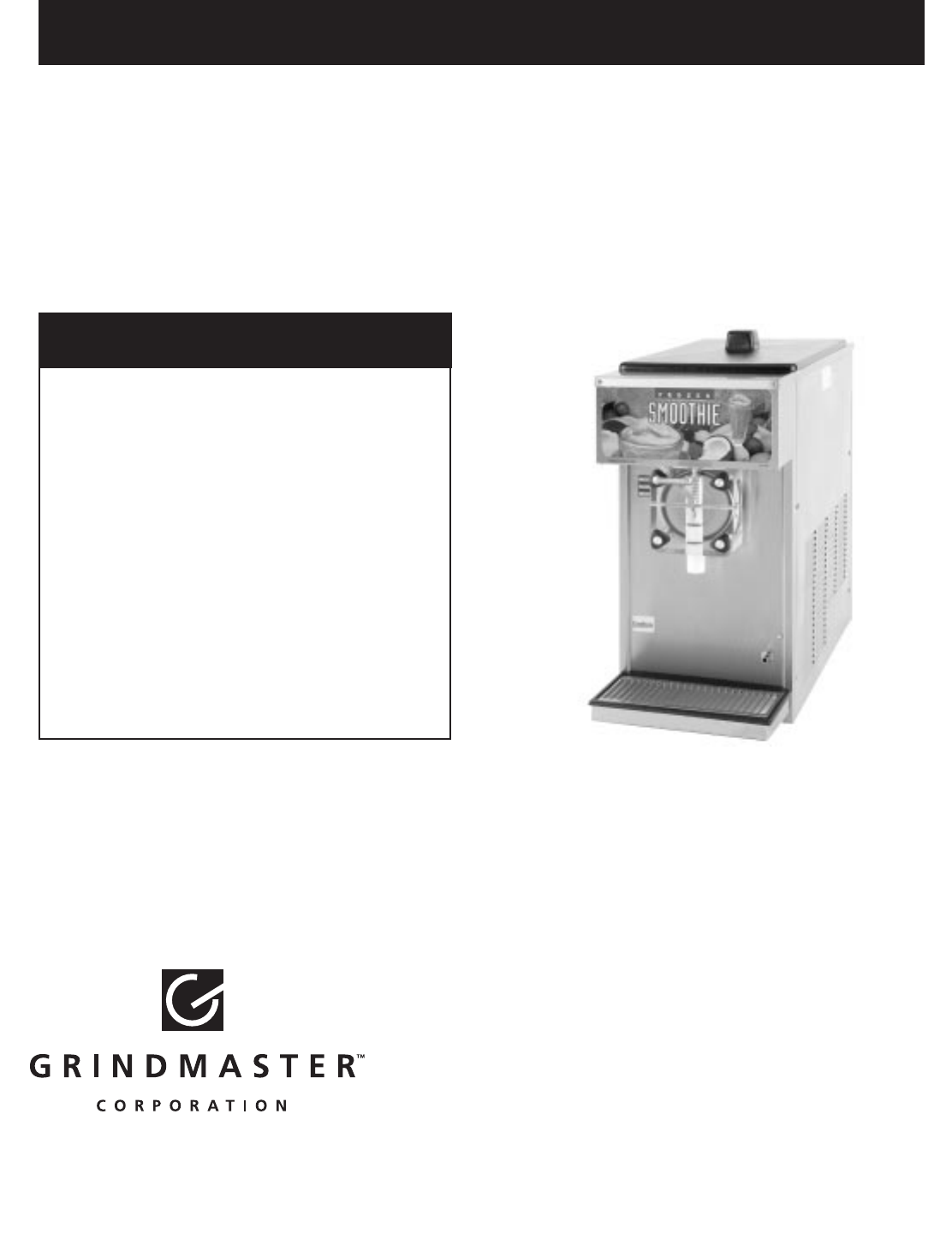
Crathco® Beverage Freezers Operation and Instruction Manual for Models 5311 & 5511 TABLE OF CONTENTS Warnings and Safety Precautions..................2 Installation ...................................................2-5 Operating and Adjustments ......................5-10 Care and Cleaning ..................................11-16 Maintenance Service ..............................16-20 Troubleshooting.......................................21-22 Exploded Views.......................................
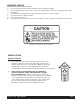
WARNING LABELS OPERATOR'S SAFETY PRECAUTIONS 1) Read and understand the operating instructions in this manual thoroughly. 2) Note all warning labels on the freezer. If any of the warning labels are missing or damaged replace them immediately. 3) Do not wear loose fitting garments or jewelry which could cause a serious accident. 4) Stay alert at all times during operation. 5) Keep operating area clean. 6) Do not operate freezer if any excessive noise or vibration occurs.
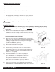
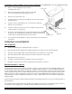
Removal from Carton and Pallet 1) Remove staples or cut cardboard box around the stapled area. 2) Pull the cardboard box up off machine. 3) Remove the Styrofoam packing and the plastic bag. 4) Remove both side panels with screwdriver. 5) Use a wratchet with a 3 inch extension and a 7/16 socket to remove the shipping bolts (connecting the machine to the pallet) located on both sides of the frame bottom plate. 6) Supporting all four sides, lift machine up and place in appropriate area.
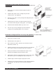
Installation of Concealed Air Filter Accessory Kit (optional) (Part #s W089.0200 Stainless Steel, W089.0208 Black) 1) Remove the four screws that hold the right side panel on the machine. 2) Install the filter panel over the existing side panel and reinstall screws. (See Figure D) 3) Open top cover of filter cover by raising and rotating away from the existing panel. 4) Slide filter into top of filter cover with removal clip up and the air flow arrows facing the existing panel.
Installation of Spinner/Mixer Accessory Kit (optional) (Part #W089.0053-115V) (Part # W0890124-220V) 1) Turn to "off" and unplug the freezer from the electrical power source. 2) Remove the white plastic plugs covering the threaded holes on the right front panel (facing the freezer). 3) Remove the electrical box cover. 4) Feed the spinner electrical wires through the 7/8” hole in the spinner mounting bracket.
Carburetor Assembly Your new freezer uses a metering device, known as a carburetor, to feed the proper ratio of mix and air into the freezing cylinder. For products such as dairy based shake mixes, the proper mix to air ratio is generally accepted to be two parts mix to one part air. This proportion yields a finished product that is both tasty and profitable. At this ratio, one gallon of liquid mix will yield a volume of one and one-half gallons of frozen product.
Computing Overrun (cont.) 3) Draw a heaping cup of frozen product that contains no air pockets. Note: Use a spatula or other device to help fill the cup completely. Avoid tamping the cup as this artificially reduces overrun. 4) Use a straight edge to scrape off excess product flush with the rim of the cup and weigh the cup. 5) Subtract the cup weight and use the overrun formula to determine overrun.
Mix Low Function (cont.) buzzer is out of the circuit and the light will illuminate fully again. After the 10-minute cycle the mix out safety function is activated making the unit inoperable. The machine is placed into the standby mode to prevent any damage to the machine from running dry of product. The unit can be reset back to the freeze mode by simply adding mix into the hopper. 1.
Product Consistency Adjustment (cont.) 4) When making adjustments to a thicker (colder) setting, dispense approximately 16 ounces (1/2 liter) of product and recheck consistency after the compressor has cycled off. 5) If the consistency is still not correct, repeat steps 2 and 3. "Standby" - Freezing Cylinder Temperature Adjustment 1) Remove the front electrical box cover. (See Figure C).
Consistency Control - Overview (cont.) In the “standby” mode the control board senses the temperature of the product in the barrel. The drive motor is cycled on time only. It will operate for 2 minutes ON then 18 minutes OFF as long as it is in “standby”. The compressor and drive motor are cycled independently for the barrel in the “standby” mode. Once the barrel thermister signals to the board, the board will start the compressor and the barrel solenoid valve will open as refrigeration is required.
CARE AND CLEANING Note: Each time the freezer is disassembled, all internal freezer components must be thoroughly washed, scoured and sanitized using procedures recommended by your local health department. In lieu of local health department recommendations, use a three compartment sink; one compartment to wash parts in detergent, one compartment to rinse, and one to sanitize. Drain and Rinse 1. If the freezer is empty, proceed to Cleaning Following Complete Disassembly of Unit or Daily Cleaning Procedure.
Daily Cleaning Procedure (cont.) Note: The best way to remove an “O” Ring is to first wipe off all of the lubricant using a clean paper towel. Pinch the “O” Ring upward with a dry towel between your index finger and thumb. When a loop is formed in the “O” Ring, roll it out of the groove with your other thumb. Always remove the “O” Ring farthest from the end of the plunger first. (See figure M). 2. Take all components to the cleaning area. 3. Carefully inspect the “O” Rings and replace if necessary.
Sanitizing Carburetor and Valve Components (cont.) 8. Slide the valve plunger spring over the small end of the valve plunger and, using another clean piece of paper toweling, pick up the valve plunger at the outlet end and insert plunger and spring into the valve body (figure Q). 9. Push up on the valve plunger and insert the stainless steel handle (figure R). Figure Q Installing Plunger and Spring 10. Insert the dispensing valve handle retaining pin (figure S) Sanitizing and Refilling 1.
Sanitizing and Refilling (cont.) 11. Watch the product flowing out of the dispensing valve and close the Valve when the sanitizer remaining in the cylinder has been purged by the new mix. 12. Use a clean piece of paper toweling to insert the sanitized carburetor assembly into the inlet hole in the hopper (figure V). 13. Fill mix storage hopper with fresh product. 14. Turn front panel switch to “ON”. Allow approximately 20 to 30 minutes for the freezer to reach proper consistency.
Cleaning Following Complete Disassembly of Unit (cont.) IMPORTANT: After disassembly, thoroughly scour each part of the freezer in a warm mild detergent solution including the inside of the freezing cylinder and the mix storage hopper. Rinse each part with cleanwater. Prepare a minimum of 3 1/2 gallons (13 liters) of sanitizing solution (Divorsol CX or equivalent) following the manufacturer's instructions. Note: Add 3 ounces (85.
Reassembly (cont.) 5. Disassemble the carburetor assembly and remove the O-Rings. Wash and sanitize all parts. 6. Reinstall and lubricate the O-Rings and slip on the outer tube if equipped. (See Figure EE.) Figure EE Thick product carb tube Standard carb tube Sanitizing and Refilling 1. Low overrun carb tube Prepare a minimum of 3 1/2 gallons (13 liters) of sanitizing solution (Diversol CX or equivalent) following the manufacturer's instructions.
How to Clean Exposed Filter: 1. Slide exposed filter out of the rails by pulling forward on the filter. It is recommended to remove the filter by using the palm of your hand and applying even pressure to the face of the filter. 2. Clean filter with liquid soap and water. 3. Soak filter for 15 minutes. 4. Rinse filter with heavy stream of water, opposite the direction of air flow. Allow filter to dry. 5. Slide the filter into the rails until the filter contacts the stop on the top rail.
Annual Maintenance (cont.) 4. Remove dasher assembly, inspect stator bearings and replace shaft seal set. (See Care and Cleaning). 5. Remove rear panel and inspect "V" belt. 6. Inspect the drive shaft square hole for wear (rounding-out). 7. Check drive shaft and motor shaft bearings for excessive wear. 8. Reinstall side and back panels. 9. Re-connect power supply. Belt Adjustment ! CAUTION: Unplug the machine before performing any adjustments.
5311 FREEZER SPECIFICATIONS: Circuit NEMA# NEMA 5-20R Electrical 115 volt, 60 Hz, 1 Phase Dedicated 20 Amp circuit 1/4 hp, Capacitor Start/Run Drive Motor Compressor Cooling Actual Weight Mix Hopper Capacity Freezing Cylinder Cap. Refrigerant Refrigerant Charge High Side (approximate operating pressure) Low Side (approximate operating pressure) High Side Design Pressure 3/4 hp Air Cooled (Optional Water Cooled) 175 lbs. (79.4 kg) 5 gallons (18.9 liters) 1 1/2 gallons (5.
Part Description Monthly Every 3 Months Every 6 Months Shaft seal Drive shaft Drive belts Scraper blades on dasher Annually Quantities to be Replaced Inspect & replace if necessary 1 Inspect & replace if necessary 1 Inspect & replace if necessary 1 Inspect & replace if necessary 2 Square cut o-ring on valve body/face plate Inspect & replace if necessary 1 Front stator flange bearing Inspect & replace if necessary 1 Inspect & replace if necessary 1 Rear stator flange bearing Dispen
TROUBLESHOOTING ! Only a qualified service technician should perform Electrical and mechanical adjustments or repairs. Always disconnect power before attempting any maintenance procedures.
TROUBLESHOOTING (cont.
Exploded View Model 5311 Optional Dasher Part #0430026 Optional X-large drip pan for units with spinners Optional Thick Product plunger Crathco® 5311 & 5511 Manual Item Part Number 1 5 10 22 23 25 27 30 32 33 34 35 36 37 38 39 44 48 49 58 61 100 107 120 121 137 138 139 140 141 142 W0110002 W0210171 W0520063 W0520064 W0520065 W0340022 W0340058 W0340210 W0389001 W0430024 W0430028 W0430032 W0430089 W0450008 W0450209 W0451067 W0520094 W0480445 W0480450 W0572286 W0572340 W0630711 W0650913 W0212081 W14310
Exploded View Model 5511 Item 1 5 10 22 23 27 30 32 33 34 35 36 37 38 39 44 45 46 47 48 49 58 61 100 107 120 121 136 137 138 Part Number Description W0110002 W0210171 W0520063 W0520064 W0520065 W0340058 W0340210 W0380025 W0430024 W0430028 W0430032 W0430089 W0450053 W0450209 W0451067 W0520094 W0472062 W0472063 W0631632 W0480445 W0480450 W0572452 W0572454 W0630711 W0650913 W0212000 W1431084 W0201335 W0570617 W0570619 Valve Stud Frame Assembly Stainless Steel Rear Panel Stainless Steel Side Panel Left Sta
Exploded View Model 5311 Base Assembly Item Part Number Description 1 2 3 4 5 6 7 8 9 10 11 12 14 W0210169 0W200123 W0200256 W0200411 W0200412 W0200413 W0201079 W0210041 W0320019 W0320209 W0320286 W0321013 W0380009 Motor Cradle Compressor Condenser Fan Mount Bracket Compressor Spacer Compressor Grommet Fan Shroud Frame Bottom Plate Drive Motor Fan Motor Fan Blade Motor Adj.
Exploded View Model 5511 Base Assembly Item 1 2 3 4 5 6 7 8 9 10 11 12 13 14 15 18 20 21 23 24 27 28 29 30 31 32 33 Part Number Description W0210169 W0200133 W0200256 W0200411 W0200412 W0200413 W0201079 W0210041 W0320020 W0320220 W0320286 W0321013 W0671017 W0380009 W0450016 W0321025 W0611074 W0611082 W0611246 W0610657 W0671018 W0671021 W0671022 W0340111 W0630421 W0610559 W0611248 Motor Cradle Compressor Condenser Fan Mount Bracket Compressor Spacer Compressor Grommet Fan Shroud Frame Bottom Plate Drive
5311 Base Assembly Refrigeration Item 1 2 3 4 5 6 7 8 9 10 11 12 13 14 15 16 17 18 19 20 Part Number Description W0650501 W0200314 W0650112 W0200123 W0200256 W0650104 W0201120 W0201331 W0620109 W0201114 W0201113 W0201323 W0620102 W0620110 W0201324 W0201325 W0201326 W1650002 W0620103 W0201039 Crathco® 5311 & 5511 Manual Access Valve Capillary Tube, .042 x 12 Ft.
5511 Base Assembly Refrigeration Item Part Number Description 1 2 3 4 5 6 7 10 11 12 13 14 15 16 17 18 19 20 21 22 23 24 25 26 27 28 29 30 31 Crathco® 5311 & 5511 Manual W0650501 W0200301 W0650112 W0200133 W0200256 W0650107 W0201120 W0201114 W0201113 W0201323 W0620102 W0620110 W0201324 W0201325 W0201326 W1650002 W0620125 W0201112 W0201371 W0620123 W0201372 W0201373 W0201155 W0650428 W0201220 W0201153 W0201151 W0620112 W0201152 Access Valve Capillary Tube Filter Drier Compressor Condenser Automatic Exp
Exploded View Probe Assembly S.
Crathco® 5311 & 5511 Manual Page 30 5000 SeriesThick Product Plunger (W0480463) 5000 Series Standard Product Plunger (W0480462) CHECK LIST Slush Cocktail Carb Tube Assy.
(CR) 5311 Electrical Components Item HS LBS & RBS FU FM DM 101 100 R1 R2 TR SW2 SC RC CR SW1 FU2 CB1 FU1 B LT1 LT1 TB1 66 67 65 Crathco® 5311 & 5511 Manual Part Number W1650004 W1650004 WI570616 W0320209 W0320019 W0570712 W0570935 W0570655 W0570655 W0570659 W0570939 W0570603 W0570617 W0570693 W0570934 W0570823 W0650913 W0570842 W0570045 W0570043 W0570044 W0570235 W1570010 W1570011 W1570012 Description HOPPER SOLENOID BARREL SOLENOID FUSE HOLDER FAN MOTOR DRIVE MOTOR POWER CORD SERVE SWITCH DRIVE MOTOR
5511 Electrical Components 5511-0102-057-3-20-00 Crathco® 5311 & 5511 Manual Page 32
(CR) (CR) (CR) 5311 Front Electrical Box (CR) Crathco® 5311 & 5511 Manual Page 33
5511 Front Electrical Box 5511-0101-057-3-20-00 Crathco® 5311 & 5511 Manual Page 34
5311 Electrical Box Item 1 2 3 4 5 6 7 8 9 10 11 Part Number W0570603 W0570617 W0570655 W0570916 W0570638 W0570934 W0572451 W1570901 W0570423 W0572342 W0650913 Description Start Capacitor Run Capacitor Contactor Reed Switch Compressor Relay On/Off Switch Electrical Box Mode Switch Terminal Strip Circuit Board Support Circuit Board Item 12 13 14 15 16 17 18 19 20 21 22 Part Number W0570043 W0570044 W0630006 W0630811 W0631629 W1570616 W0570823 W0570842 W0630427 W0572704 W0572705 Description Light Bulb
5311 Spinner Hook-Up Wiring Diagram Crathco® 5311 & 5511 Manual Page36
5511 Spinner Hook-Up Wiring Diagram 5511-0100-057-9-14-00 Crathco® 5311 & 5511 Manual Page 37
5311 Compressor Wiring Diagram 5511 Compressor Wiring Diagram 5511-0106-057-3-20-00 Crathco® 5311 & 5511 Manual Page 38
5311 Ladder Diagram 115V 60 hz Crathco® 5311 & 5511 Manual Page 39
5511 Ladder Diagram 208/230V/50 Hz 5511-0103-057-3-20-00 Crathco® 5311 & 5511 Manual Page 40
5311 Wiring Diagram Item 1 2 3 4 5 6 7 8 9 10 11 12 13 14 15 16 17 18 19 Part Number Description W0570603 W0570617 W0570655 W0570423 W0570043 W0570638 W1650004 W0650913 W0570044 W0570823 W1570616 W0570659 W0570045 W0570934 W1570901 W1572132 W0570842 W0570935 W0572704 Start Capacitor Run Capacitor Contactor 8 Pin Terminal Strip Bulb Compressor Relay Solenoid Coil Circuit Board Light Socket 3.2 Amp Fuse Fuse Holder Transformer Ballast On/Off Switch Stand-By Switch 6 Wire Cable Sub Assy.
5511 Wiring Diagram Item 1 2 3 4 6 7 10 11 12 14 15 16 17 18 19 20 21 22 *23 *24 *25 *26 *27 28 Part Number Description W0570619 W0570617 W0570655 W0570213 W0570618 W0650102 W0570823 W1570616 W0570659 W0570912 W1570901 W1572132 W0570842 W0570916 W0572704 W0570043 W0570044 W0570047 W0572500 W0572501 W0572502 W0572503 W0572504 83106 Start Capacitor Run Capacitor Contactor 8 Pin Terminal Strip Compressor Relay Solenoid Complete 3.
Refrigeration Circuit Crathco® 5311 & 5511 Manual Page 43