Shuttle® Brewer & Airpot/Shuttle® Brewers Operation and Instruction Manual For Models PB-330, PB-430, PBVSA-330, PBVSA-430, PBIC-330, PBIC-430, PB330E 230V, PB-430E 230V, PBVSA-330E 230V, PBVSA-430E 230V, PBIC-330E 230V, PBIC-430E 230V Table of Contents Warning Labels . . . . . . . . . . . . . . . . . . . . . . . . . . 3 Installation and Start-up . . . . . . . . . . . . . . . . . . . 4 Operation . . . . . . . . . . . . . . . . . . . . . . . . . . . . . . 6 Adjustments . . . . . . . . . . . . . . . . . . .
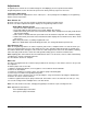
Warning Labels The following warning labels were on your dispenser when it was shipped from the factory. They should remain on your dispenser in good, readable condition at all times. If one of your labels is missing or damaged, order a replacement label immediately. Part # A546-445 Located on front splash panel and lid of machine. Located on PB-330, PB-330E 230V, PB-430, and PB-430E 230V lower front decal. Order part # A546-434 for PB-330. Order part # A546-435 for PB-430.
Installation WARNING ELECTRIC SHOCK HAZARD! Installation of this appliance should be performed by qualified service personnel only. Improper installation could result in electrocution. Set-Up/Position 1) Remove the brewer from the packing material and attach its legs. 2) Position the brewer on a strong, stable table or counter. Check the level front to back and side to side. Adjust the legs to the correct level.
Installation (cont.) Electric Hook-up The brewer is designed to operate at the specified voltage on the nameplate with a tolerance of ± 10% for voltage deviation. It is very important that the power line to the brewer be checked to make sure that the voltage is within 10% of the brewer’s rated voltage. Failure to provide adequate voltage, as defined above, will cause problems with your brewer. If the power is too low, the solenoid valves may or may not work or longer recovery time will be experienced.
Operation CAUTION HOT LIQUID HAZARD! Water used for brewing coffee is very hot. Use caution when brewing, pouring, or transporting coffee. Accidental spills may result in severe burns. 1) Place an empty, warm Shuttle on the shelf, under the brew head. Turn on the warmer if available. 2) If the Shuttle is not warm, allow the warmer to heat the Shuttle. Only a short brew of water will speed this. A cold Shuttle will significantly lower the temperature of the brewed coffee.
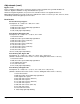
Adjustments All adjustments to machine are accessible through the front display(s). Refer to specifics below and the Programming Routine section. All values are preset at the factory and may vary brewer to brewer. Temperature Adjustment Tank temperature can be adjusted from 170°F – 205°F (77°C – 96°C) through the front display. See Programming Routine section for procedure. Brew Volume “br” Brew time can be set for each size visually. See Setting Brew Volume Procedure below.
Adjustments (cont.) Bypass “b-P” Brewer contains a bypass valve to control the amount of water to bypass coffee grounds and dilute the final brew. Bypass is available on Large and Medium brew cycles. Within the Programming Routine, the percent of the total brew volume to be bypassed can be set. Note: Adjusting bypass percent will not affect the finished brew volume. The brew cycle time, however, will be automatically reduced as bypass percent increases.
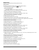
Programming (All values are preset at the factory and may vary brewer to brewer.) Settings Routine Programming For All Brewer Settings and Large Portion (refer to Table 1) 11. Press and hold both “up” and “down” arrows for 5 seconds. 12. All three “brew” lights will flash. 13. Press “Large Brew” button. Only “Large” ready light illuminates during remaining steps. 14. Display will indicate either “d F” or “d C” (Fahrenheit or Celsius). Default is “d F”. 15.
Programming For All Brewer Settings and Large Portion (cont.) Table 1 1. PRESS-AND-HOLD UP & DOWN ARROWS FOR 5 SECONDS. 2. READY LIGHTS WILL FLASH. 3. PRESS BREW BUTTON FOR LARGE "L". 4. LARGE READY LIGHT FLASHES THROUGHOUT ROUTINE. 5.
Programming (cont.) Settings Routine Programming For Medium: Brew Time, Pulse Brewing & Bypass (refer to Table 2) 11. Press and hold both “up” and “down” arrows for 5 seconds. 12. All three brew lights will flash. 13. Press “Medium Brew” button. Only “Medium” ready light illuminates during remaining steps. 14. Display will read “Br” (Brew Time). 15. Press “Medium Brew” button to go to next setting. 16. Display will read set brew time in minutes and seconds (0.01-6.00). Default is “2.40”. 17.
Programming (cont.) Settings Routine Programming For Small: Brew Time & Pulse Brewing (refer to Table 3) 11. Press and hold both “up” and “down” arrows for 5 seconds. 12. All three “brew” lights will flash. 13. Press “Small Brew” button. Only “Small” ready light illuminates during remaining steps. 14. Display will read “Br” (Brew Time). 15. Press “Small Brew” button to go to next setting. 16. Display will read set brew time in minutes and seconds (0.01-6.00). Default is “1.20”. 17.
Cleaning WARNING Burn Hazard! Hot liquids and surfaces are present in this equipment. To avoid burns use caution when cleaning. Rinse hot parts with cold water before cleaning. Use gloves or a heavy cloth when removing hot parts from brewer. After Each Brew: 1) Dispose of grounds and rinse brew basket. 2) Rinse Shuttle or airpot containers before reuse. Every Day: 1) Wash brew basket with warm soapy water. The wire basket is removable to aid cleaning.
Service The rest of this manual contains information to aid the service person who is working on this equipment. This page has information on performing common service tasks. Following this is the Troubleshooting section which can help diagnose problems which are divided into three basic systems: filling, heating, and brewing. Next is an illustrated parts breakdown which will help in the selection of repair parts.
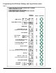
Special Control Functions User Lockout User Lockout is achieved via the position of the LOCK jumper on the board header. Locate the header on the board (shown below) and place the jumper in the desired position. In the Locked position all menus in this document are locked out, and the unit will only allow brewing functions. There are two versions of the header, 10 pin and 2 pin. Both configurations are shown below.
Factory/Field Test Menu (cont.) Step Function Operation Description 1 LED Test All LEDs ON Verify that all LEDs turn on. 2 Firmware Version Display firmware version Shows the software version of the control.
Troubleshooting The following pages are provided to help determine the cause of problems with operation of the brewers and to indicate the appropriate solution for the problems. For each problem, the possible causes should be checked in the order shown until the exact nature of the problem is determined. The following procedures must be performed by a qualified service technician. Disconnect power to machine before servicing.
Troubleshooting (cont.) Filling Problems Problem Tank does not refill Page 18 Possible Causes Service Check Remedy • No electrical power to equipment • Check for proper • Establish electrical power voltage at terminal to unit. block. Check circuit breaker on supply circuit. • No water supplied to equipment • Disconnect water supply line and ensure that water is provided to unit. Check to see that any and all valves in water line are open.
Troubleshooting (cont.) Filling Problems Problem Tank does not refill Possible Causes • Fill valve or control board is faulty Service Check Remedy • Check to ensure proper • If 6 pin connector is securely connection between attached to control board and 6 pin connector and con- all connections are secure trol board. Check and there is 24 Vac across for proper connections fill valve terminals, replace at fill valve terminals. fill valve. Drain 1 gal. (3.8L) of water from hot water faucet.
Troubleshooting (cont.) Heating Problems Problem Tank does not heat Possible Causes Service Check Remedy • Low (long) electrode coated with lime or faulty. • Disconnect electrode • Remove electrode assembly wire at quick connect and clean the probes. If (purple wire). Connect a problem is not corrected, wire from the quick conreplace electrode assembly. nect to the cabinet body. If heating begins, this is the error cause. • Connection from control board to tank body faulty.
Troubleshooting (cont.) Heating Problems Problem Tank does not heat Possible Causes Service Check Remedy • Contactor faulty. • Ensure that coil on • If the contactor coil is contactor is energized energized and there is an by ensuring that there open circuit across any of is proper voltage the contactor poles, replace between the brown and contactor. white wires attached to the relay. Check each side of the contactor (Line and Load) at each pole for continuity. • Heater faulty.
Troubleshooting (cont.) Brewing Problems Problem Brew volume too large or too small Brew volume erratic Possible Causes Service Check Remedy • Sprayhead clogged. • Visually check for clogging of holes in brewhead. • Clean all holes. • Brew valves clogged with lime deposits. • Visually inspect brew valve at hose connections. • Clean lime from valve. Seat, cup or entire valve may need replacement. • Water supply pressure or flow rate not adequate.
Troubleshooting (cont.) Brewing Problems Problem Possible Causes Service Check Remedy Brew cycle will not start • Controller faulty. • Check to see that the • If there is not 24 Vac across power is supplied to the brew valve, replace control controller by following board. instructions given in the Troubleshooting section on Filling Problems. Once touchpad and momentary switch integrity is assured (see above), initiate a brew cycle and check for 24 Vac across brew valve.
Parts List for All Precision Brew Models Models PB-330, PB-430, PBVSA-330, PBVSA-430, PBIC-330, PBIC-430 ITEM DESCRIPTION PART # Reference Front View Picture: 1 Controller PB Single 2 Relay, Heater 24vdc 3 Valve, Inlet 24vac 4 Terminal Block 5 Spray Head 6 Orifice Bypass 7 Fitting Assy Water Inlet 8 Switch Momentary ** PBIC only A530-056 (prior to May 2007); A530-059 (after May 2007) A531-072 (prior to May 2007); A71450 (after May 2007) A537-189 A531-035 APT400-010 A518-045 A718-226 A531-025 Reference
Front View (refer to key on page 24) 6 2 2 6 5 5 1 1 7 4 3 7 4 (prior to May 2007) 3 (after May 2007) Lower Warmer (refer to key on page 24) (PB-430 pictured) 23 23 20 21 21 22 Shuttle Brewers & Airpot/Shuttle Brewers 22 Page 25
Top View (refer to key on page 24) 36 38 35 36 35 42 32 34 30 Tank Lid (refer to key on page 24) 3 Heater Model shown 52 51 50 50 Page 26 Shuttle Brewers & Airpot/Shuttle Brewers
Shuttle Parts List for PB-330 and PB-430 only 6 5 4 3 2 1 ITEM DESCRIPTION PART # 1 Faucet Model ES A537-053 2 Shank w/ Chrome Bonnet A522078 3 Gauge Assembly A718-018 4 Kit, Shuttle Lid A725-092 S.S. Shuttle Cover (not shown)* A713-027 5 Lid Retaining Clip A548-142 6 Lid Stopper w/ O-Ring A548-140 A61365 * S.S.
ITEM NO. 1 2 3 4 5 6 7 8 9 Page 28 Title Stand Body Tray for Stand Vacuum Shuttle Stand Base Tray Top Self-Tapping Screw .5" Rubber Foot Plastic Insert Self-Tapping Scres .75" 2 5 1 6 9 4 8 PART NUMBER A548-157 A548-159 VS-1.5 A548-158 A517-018 A539-217 A548-161 A548-162 A539-218 3 7 VS-1.5S VS-1.5S/QTY. 1 1 1 1 1 4 4 3 3 4 ITEM NO. 1 2 3 4 5 6 7 8 5 2 Title Stand Body Tray for Stand Stand Base Tray Top Stand, Top Plate NUT M4 W Nylon Insert Self-Tapping Screw .
Cleaning & Sanitizing Instructions for Model VS-1.5(S) These cleaning and sanitizing instructions are only a guideline to be used for the cleaning and sanitizing of the VS-1.5S and VS-S with VS-1.5. In-house cleaning and sanitizing methods may be more effective. Grindmaster assumes no responsibility for the food born illness and/or sickness caused by using improper sanitizing methods. For cleaning and sanitizing of the VS-1.5S and VS-S with VS-1.5 the three-sink method is recommended.
Wiring Diagram - Precision Brew 430 Series Prior to May 2007 Models PB-430, PBVSA-430, and PBIC-430 Page 30 Shuttle Brewers & Airpot/Shuttle Brewers
Wiring Diagram - Precision Brew 330 Series Prior to May 2007 Models PB-330, PBVSA-330, and PBIC-330 Shuttle Brewers & Airpot/Shuttle Brewers Page 31
Wiring Diagram Prior to May 2007 PB-430E 230V, PBVSA-430E230V, PBIC-430E 230V (Single or Three Phase Models) Page 32 Shuttle Brewers & Airpot/Shuttle Brewers
Wiring Diagram Prior to May 2007 PB-330E 230V, PBVSA-330E 230V, PBIC-330E 230V Brewers Shuttle Brewers & Airpot/Shuttle Brewers Page 33
Wiring Diagram - Precision Brew 430 Series After May 2007 Models PB-430, PBVSA-430, and PBIC-430 Page 34 Shuttle Brewers & Airpot/Shuttle Brewers
Wiring Diagram - Precision Brew 330 Series After May 2007 Models PB-330, PBVSA-330, and PBIC-330 Shuttle Brewers & Airpot/Shuttle Brewers Page 35
Wiring Diagram After May 2007 PB-430E 230V, PBVSA-430E230V, PBIC-430E 230V (Single or Three Phase Models) Page 36 Shuttle Brewers & Airpot/Shuttle Brewers
Wiring Diagram After May 2007 PB-330E 230V, PBVSA-330E 230V, PBIC-330E 230V Brewers Shuttle Brewers & Airpot/Shuttle Brewers Page 37
Wiring Diagram - Heater Configuration (3 Heater) Page 38 Shuttle Brewers & Airpot/Shuttle Brewers
Wiring Diagram - Heater Configuration (1 Heater) Shuttle Brewers & Airpot/Shuttle Brewers Page 39
Grindmaster® Coffee Grinders and Brewers • PrecisionBrew™ Brewing Systems • Espressimo® Espresso Machines Crathco® Hot Beverage Dispensers • Crathco® Cold and Frozen Beverage Dispensers • AMW Coffee and Tea Systems Tel (502) 425-4776 • Fax (502) 425-4664 • 1-800-695-4500 (USA & Canada only) P.O. Box 35020 • Louisville, KY 40232 • USA © Grindmaster Corporation, 2003 0607 Form # AM-344-04 www.grindmaster.com • email: info@grindmaster.