Crathco® Beverage Freezers Operation and Instruction Manual for Models 5512 & 5512E TABLE OF CONTENTS Operator’s Safety Precautions . . . . . . . . . . . . .3 Installation . . . . . . . . . . . . . . . . . . . . . . . . . . .3-5 Operation . . . . . . . . . . . . . . . . . . . . . . . . . . .6-8 Product Tips . . . . . . . . . . . . . . . . . . . . . . . . .8-9 Consistency Control . . . . . . . . . . . . . . . . . .9-10 Care & Cleaning . . . . . . . . . . . . . . . . . . . .11-15 Maintenance . . . . . . . .
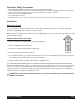
Operator's Safety Precautions 1. 2. 3. 4. 5. 6. Read and understand the operating instructions in this manual thoroughly. Note all warning labels on the freezer. If any warning labels are missing or damaged replace them immediately. Do not wear loose fitting garments or jewelry which could cause a serious accident. Stay alert at all times during operation. Keep operating area clean. Do not operate freezer if any excessive noise or vibration occurs. Contact your authorized service agent.
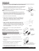
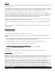
Installing Your Unit ! CAUTION: Do not alter or deform the plug in any way. Altering or deforming plug may damage unit and will void warranty! Receptacle NEMA 6-20R required for Model 5512. 1. Place freezer in a location that allows adequate space at each side and above for proper air circulation. Minimum clearance is: 6” (15 cm) on both sides, 4” (10 cm) at back, and 8" (20 cm) above the freezer. See figure B.
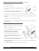
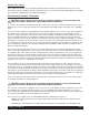
Installation of Exposed Filter Accessory Kit (optional) (Part #W089.0206) 1. Remove the four panel screws. 2. Pull the bottom of the panel out. 3. Run a bead of the silicone adhesive at the inside back of the bottom filter channel. (2) 4. Install the channel over the end of the side panel so the adhesive in the channel contacts the bottom edge of the side panel. Figure F 5. Put the panel with the channel added, back in place on the machine and reinstall the two lower panel screws. 6.
Operation & Adjustments How to Operate: 1) Sanitize unit following the cleaning instructions on page 12. 2) Fill hopper with product. Allow barrel to fill with product to the proper level, then install carb tube. 3) Turn power switch (toggle switch located underneath the electrical box) to "on" position. 4) Turn mode switch (rocker switch located next to power switch) to “freeze” position. 5) Allow product to freeze in barrel. 6) To dispense product pull down valve handle and release when done.
Overrun Overrun is the increase in product volume, expressed as a percentage, resulting from the entrapment of air in liquid mix as it is frozen. The rotating dasher blends air into the mix as it is frozen resulting in increased frozen product volume. For example, if one gallon (1) (4.4 liters) of liquid mix is poured into a freezer and one and a half gallons (1/2) (6.6 liters) of frozen product is drawn out, the result is a fifty percent volumetric increase, or a fifty (50%) percent “overrun”.
Standby Switch The "STANDBY" switch allows the operator to retain optimum product quality and conserve energy during extended non-draw periods. The Stand-by mode keeps the mix in the hopper at a safe storage temperature and allows the product in the freezing cylinder to return to a refrigerated liquid state. Switching back to "ON" quickly returns the product in the freezing cylinders to proper serving consistency. At the start of the “STANDBY” period: 1. Fill the hoppers with fresh mix. 2.
Product Tips (cont.) Some cappuccino or latte’ mixes contain dairy products which can spoil if not refrigerated. If the freezer is to be turned off at night these products must be removed from the freezer. Contact your local health department regarding their regulations regarding proper mix handling and storage. Consistency Control - Overview ! CAUTION: SHOCK HAZARD! THIS ADJUSTMENT REQUIRES REMOVAL OF THE ELECTRICAL BOX COVER AND SHOULD BE MADE BY A QUALIFIED SERVICE TECHNICIAN.
Consistency Control -Overview (cont.) WASH (D3) - Illuminated when the mode switch is in the wash or "Clean" position. FREEZE (D4) - Illuminated when the mode switch is in the "Freeze" mode. DISPENSE (D5) - Illuminated when the dispensing valve is open calling for both the compressor and drive motor to operate. GREEN CONSISTENCY (D6) - Off when the motor and compressor are off. Illuminated when the compressor and dasher are bringing product to preset consistency.
! CAUTION: THIS CONTROL SETTING IS VERY SENSITIVE SO ALWAYS MAKE SMALL ADJUSTMENTS. IF YOU VISUALIZE THIS CONTROL AS A CLOCK FACE, A ONE HOUR CHANGE WILL MAKE A NOTICEABLE DIFFERENCE IN HOPPER PRODUCT TEMPERATURE. A RECOMMENDED SETTING IS 11:00. Care & Cleaning NOTE: Each time the freezer is disassembled, all internal freezer components must be thoroughly washed, scoured and sanitized using procedures recommended by your local health department.
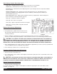
Care & Cleaning (cont.) 3. Using medium sized brush (supplied with freezer) clean the bottom of the valve body and the inside of the plunger bore with detergent solution taking care to remove all remaining lubricant (see figure K). Repeat for other side. Sanitizing Carburetor and Valve Components 1. Re-assemble carburetor assembly installing the two “O” Rings at the bottom of the carb tube. Figure L Sanitize Valve Body 2. Place the carburetor assembly in the bottom of the hopper. 3.
Sanitizing & Refilling (cont.) 5. Use a clean piece of paper toweling to pick up the large end of the carburetor from the bottom of the hopper taking care not to touch the sanitized carburetor with your bare hands. 6. Apply the lubricant on the other piece of paper toweling to the two “O” Rings on the bottom of the carburetor assembly (see figure S). 7. Place the lubricated carburetor assembly on a clean piece of paper toweling. Figure R Lubricate Carb Tube 8.
Cleaning Following Complete Disassembly of Unit (cont.) IMPORTANT: After disassembly, thoroughly scour each part of the freezer in a warm mild detergent solution including the inside of the freezing cylinder and the mix storage hopper. Rinse each part with clean water. Prepare a minimum of 3 1/2 gallons (13 liters) of sanitizing solution (Divorsol CX or equivalent) following the manufacturer's instructions. NOTE: Add 3 ounces (85.
Sanitizing and Refilling 1. Prepare a minimum of 3-1/2 gallons (13 liters) of sanitizing solution (Divorsol CX or equivalent) following the manufacturer's instructions. NOTE: Add sanitizer to 3-1/2 gallons of water (warm) to achieve a concentration of 200 parts per million. 2. Pour sanitizing solution into the mix storage hopper and allow the solution to fill freezing cylinder. Use a brush to clean the hopper sides and bottom. (Repeat steps 1 & 2 for opposite side.) 3.
How to Clean Concealed Filter: 1. For concealed filters lift lid and pull up on filter tab to remove filter. 2. Clean filter with liquid soap and water. 3. Soak filter for 15 minutes. 4. Rinse filter with heavy stream of water, opposite the direction of air flow. Allow filter to dry. 5. Slide filter into top of filter cover with removal clip up and the air flow arrows facing the existing panel. ! CAUTION: Disconnect power for maintenance.
Belt Adjustment ! CAUTION: UNPLUG THE MACHINE BEFORE PERFORMING ANY ADJUSTMENTS. THIS PROCEDURE MUST BE DONE BY A QUALIFIED TECHNICIAN. Figure CC Check the belt tension. The proper belt deflection is 1/2" over all. If the deflection is more than 1/2" the motor will need to be lowered. If the deflection is less than 1/2" the motor will need to be raised. Follow this procedure to adjust the motor to achieve proper belt tension. 1. Unplug the machine and remove both side and the rear panels. 2.
Freezer Specifications MODEL 5512 Circuit NEMA # 6-2OR Electrical 208 volt, 60 Hz, 1 Phase Dedicated 20 Amp circuit 1/2 hp, Capacitor Start / Run Drive Motor Compressor Cooling Actual Weight Mix Hopper Capacity Freezing Cylinder Cap. Refrigerant Refrigerant Charge High Side (approximate operating pressure) Low Side (approximate operating pressure) High Side Design Pressure) Low Side Design Pressure) 1 hp Air Cooled 260 lbs. (118 kg) 3 gallons (11.35 liters) per side 1 1/2 gallons (5.
Part Description Monthly Every 3 Months Every 6 Months Shaft seal Annually Quantities to be Replaced Inspect & replace if necessary 2 Inspect & replace if necessary 2 Inspect & replace if necessary 2 Drive shaft Drive belts Scraper blades on dasher Inspect & replace if necessary Square cut o-ring on valve body/face plate Front stator flange bearing Rear stator flange bearing 4 Inspect & replace if necessary 2 Inspect & replace if necessary 2 Inspect & replace if necessary 2 Dispens
Troubleshooting Guide ! Only a qualified service technician should perform electrical and mechanical adjustments or repairs. Always disconnect power before attempting any maintenance procedures.
PROBLEM PROBABLE CAUSE SOLUTION Excessive dispensing valve leakage Worn or defective O-Rings Replace and lubricate at each cleaning Scraping sound during freeze down Frozen product scraping off of cylinder walls Clicking sound Low voltage Normal sound during freeze down, goes away when product is frozen to proper consistency Connect freezer to dedicated circuit of proper rating Thumping sound from inside freezer Extension cord or improperly sized electrical wire Connect freezer directly to powe
Exploded View Model 5512 Final Assembly Exploded View Model 5512-E Final Assembly Page 22 Crathco® 5512 Manual
Exploded View Model 5512 Stock Assembly Item 173 172 171 147 118 117 110 85 84 83 73 54 52 48 45 37 36 Part Number W0520081 W0520080 W0520082 W0572411 W0572371 W0572372 W0572358 W0631621 W0631620 W0631230 W0611728 W0211213 W0211212 W0572298 W0471134 W0480450 W0480445 Crathco® 5512 Manual Description PANEL, LH PANEL, REAR PANEL, RH LEFT ELEC.
Exploded View Model 5512-E Stock Assembly Item 173 172 171 147 118 117 110 85 84 83 73 54 52 48 45 37 36 Part Number W0520083 W0520084 W0520082 W0572411 W0572371 W0572372 W0572358 W0631621 W0631620 W0631230 W0611728 W0211213 W0211212 W0572298 W0471134 W0480450 W0480445 Page 24 Description PANEL, LH PANEL, REAR PANEL, RH LEFT ELEC.
Exploded View Model 5512 Base Assembly Item 24 23 22 21 20 19 18 17 16 15 14 13 Part Number W0340111 W0611246 W0611235 W0611082 W0611074 W0611055 W0610559 W0610264 W0610110 W0451000 W0380009 W0321022 Description RUBBER BUMPER 1/4 LOCKWASHER 3/16 FLAT WASHER 5/16-18 FLANGE NUT 1/4-20 HEX NUT 10-24 HEX NUT 1/4-20 X 1 CAP SCREW 10-24 X 1/4 TRUSS HD. #8 X 3/8 PAN HD.
Exploded View Model 5512-E Base Assembly Item 24 23 22 21 20 19 18 17 16 15 14 13 Page 26 Part Number W0340111 W0611246 W0611235 W0611082 W0611074 W0611055 W0610559 W0610264 W0610110 W0451000 W0380009 W0321023 Description RUBBER BUMPER 1/4 LOCKWASHER 3/16 FLAT WASHER 5/16-18 FLANGE NUT 1/4-20 HEX NUT 10-24 HEX NUT 1/4-20 X 1 CAP SCREW 10-24 X 1/4 TRUSS HD. #8 X 3/8 PAN HD.
Exploded View Model 5512 Base Assembly Refrigeration Item Part Number 34 W0650428 33 W0201417 32 W0201416 31 W0201415 30 W0201414 28 W0201412 27 W0201411 26 W0201410 25 W0201409 24 W0201408 23 W0201407 22 W0201406 21 W0650112 20 W0201405 19 W0201404 18 W0201403 Description HIGH PRESSURE CUTOUT, 500# HOT GAS LINE 1/4” HOT GAS LINE 3/8” ACCESS VALVE LINE SUCTION LINE R.H. EXPANSION VALVE LINE EXPANSION VALVE LINE CONDENSER/DRIER LINE DRIER LINE L.H. EXP. VALVE LINE R.H. EXP. VALVE LINE L.H.
Exploded View Model 5512 Base-E Assembly Refrigeration Item Part Number 34 W0650428 33 W0201417 32 W0201416 31 W0201415 30 W0201414 28 W0201412 27 W0201411 26 W0201410 25 W0201409 24 W0201408 23 W0201407 22 W0201406 21 W0650112 20 W0201405 19 W0201404 18 W0201403 Page 28 Description HIGH PRESSURE CUTOUT, 500# HOT GAS LINE 1/4” HOT GAS LINE 3/8” ACCESS VALVE LINE SUCTION LINE R.H. EXPANSION VALVE LINE EXPANSION VALVE LINE CONDENSER/DRIER LINE DRIER LINE L.H. EXP. VALVE LINE R.H. EXP. VALVE LINE L.H.
Exploded View Probe Assembly S.
Page 30 Crathco® 5512 Manual CHECK LIST (W0631230) Smooth Shiny Side 2 Rough Side of Ceramic CRATHCO MACHINE ASSEMBLY 1
Exploded View Model 5512 Electrical Components 5512 ELECTRICAL COMPONENT FRONT PANEL LOWER LEFT ELECTRICAL BOX UPPER LEFT ELECTRICAL BOX Item Part Number Description LHS & RHS LBS & RBS PS FU1-4 FM DM1 & DM2 101 W1650002 W1650002 W0650428 W1570616 W0320216 W0321022 W0570712 HOPPER SOLENOIDS BARREL SOLENOIDS HIGH PRESSURE CUT-OUT FUSE HOLDERS FAN MOTOR DRIVE MOTORS 100 R1 & R2 R3 & R4 TR1 & TR2 W0570916 W0570677 W0570655 W0570873 SW2 & SW3 SC RC W0570939 W0570672 W0570673 RELAY SWITCH SWITCHING
Exploded View Model 5512-E Electrical Components 5512-E ELECTRICAL COMPONENT FRONT PANEL LOWER LEFT ELECTRICAL BOX UPPER LEFT ELECTRICAL BOX Item Part Number Description LHS & RHS LBS & RBS PS FU1-4 FM DM1 & DM2 101 W1650002 W1650002 W0650428 W1570616 W0320216 W0320031 W0570714 HOPPER SOLENOIDS BARREL SOLENOIDS HIGH PRESSURE CUT-OUT FUSE HOLDERS FAN MOTOR DRIVE MOTORS 100 R1 & R2 R3 & R4 TR1 & TR2 W0570916 W0570677 W0570655 W0570873 SW2 & SW3 SC RC W0570939 W0570672 W0570673 SERVE SWITCH SWITCH
Model 5512 Electrical Components Front Electrical Box Crathco® 5512 Manual Page 33
Model 5512-E Electrical Components Front Electrical Box Page 34 Crathco® 5512 Manual
Model 5512 Contactor Box Item Part Number 1 2 3 4 5 6 7 8 W0572373 W0570655 W0570618 W0570617 W0570619 83106 W0630802 W0610264 9 10 11 W0340110 W0610014 W0610138 12 W0572417 13 W0572413 Description CONTACTOR BOX CONTACTORS COMPRESSOR RELAY RUN CAPACITOR START CAPACITOR RELAY CABLE TIE, 7.375” NATURAL (NOT SHOWN) SCRW, 10-24 X 1/4 TRUSS HD PH (NOT SHOWN) RUBBER GROMMET 6.
Models 5512 & 5512-E Electrical Box Item Part Number 29 W0572415 28 W0572414 27 W0572412 26 W0572411 25 W0570206 24 W0572703 23 W0572700 22 W0570916 21 W0631630 20 W0572357 19 W1631508 18 W0630804 17 W0630801 16 W0630008 15 W0611037 Description ELECTRIC BOX WIRE BUNDLE RIGHT ELECTRICAL BOX HARNESS RIGHT SIDE HARNESS LEFT ELECTRICAL BOX HARNESS TERM, 2-520184-2 RECEPTACLE SERVE SWITCH BRACKET SERVE SWITCH BRACKET REED SWITCH (NORMALLY OPEN) LIGHTED ELECTRICAL BOX LENS ELECTRICAL BOX WIRE SADDLE WIRE TIE CA
Models 5512 & 5512-E Spinner Wire Hookup Models 5512 & 5512-E Compressor Contact Detail Crathco® 5512 Manual Page 37
Model 5512 Ladder Diagram Page 38 Crathco® 5512 Manual
Model 5512-E Ladder Diagram Crathco® 5512 Manual Page 39
Model 5512 Wiring Diagram Item Part Number 121 120 105 104 103 102 W0570655 83106 W0650428 W1570616 W0320220 W0321022 101 W0570712 100 W0570916 99 98 97 96 W0570677 W0570659 W0570939 W0570619 Page 40 Description CONTACTORS RELAY CONTACTOR HIGH PRESSURE CUT-OUT FUSE HOLDERS FAN MOTOR REQUIRE 2 W0570308 DRIVE MOTORS REQUIRE 4 W0570205 2 W0570206 & 1 W0570308 POWER CORD REQUIRE 2 WIRE NUTS & 1 W0570308 SERVE SWITCH REQUIRE 1 EA.
Model 5512-E Wiring Diagram Item Part Number 121 120 105 104 103 102 W0570655 83106 W0650428 W1570616 W0320216 W0320031 101 W0570714 100 W0570916 99 98 97 96 W0570677 W0570873 W0570939 W0570672 Description CONTACTORS RELAY CONTACTOR HIGH PRESSURE CUT-OUT FUSE HOLDERS FAN MOTOR REQUIRE 2 W0570308 DRIVE MOTORS REQUIRE 4 W0570205 2 W0570206 & 1 W0570308 POWER CORD REQUIRE 2 WIRE NUTS & 1 W0570308 SERVE SWITCH REQUIRE 1 EA.
Models 5512 & 5512-E Refrigeration Schematic Page 42 Crathco® 5512 Manual
Grindmaster® Coffee Grinders and Brewers • PrecisionBrew™ Brewing Systems • Espressimo® Espresso Machines Crathco® Hot Beverage Dispensers • Crathco® Cold and Frozen Beverage Dispensers • AMW Coffee and Tea Systems Tel (502) 425-4776 • Fax (502) 425-4664 • 1-800-695-4500 P.O. Box 35020 • Louisville, KY 40232 • USA www.grindmaster.com • email: info@grindmaster.