
User Manual
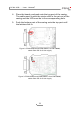

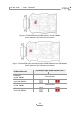
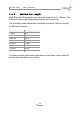
Table Of Contents

PCAN-USB – User Manual
13
3.3 Activating the Internal Termination
Only applicable to adapters from S/N 200000.
The internal termination can be activated by solder jumpers on the
circuit board to terminate one end of the CAN bus. At delivery the
termination is not activated. A High-speed CAN bus (ISO 11898-2)
must be terminated on both ends with 120 Ohms. Otherwise
disturbances may arise.
Do the following to activate the internal termination:
Risk of short circuit! Solder with great care to avoid unwanted
short circuits on the card.
Attention! Electrostatic discharge (ESD) can damage or destroy
components on the circuit board. Take precautions to avoid
ESD while handling the circuit board.
1. Open the adapter casing. Push the latches on both sides
cautiously, e.g. with a flat tip screwdriver.
2. Remove the circuit board.
3. Set both solder bridges. The following figures show the
positions of the solder fields.
4. Place the board overhead onto the top part of the casing.
The cable must lie with the strain relief in the cut-out of the
casing and the LED must be in the corresponding hole.
5. Push the bottom part of the casing onto the top part until
the latches click in.