
User Manual
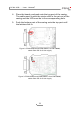

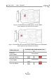
Table Of Contents

PCAN-USB – User Manual
11
4. Place the board overhead onto the top part of the casing.
The cable must lie with the strain relief in the cut-out of the
casing and the LED must be in the corresponding hole.
5. Push the bottom part of the casing onto the top part until
the latches click in.
Figure 2: PCAN-USB board (IPEH-002021) to S/N 199999,
solder field JP3 for 5-Volt supply
Figure 3: PCAN-USB board (IPEH-002021) from S/N 200000,
solder field JP3 for 5-Volt supply