
User manual


H82.0.01.6C-03 Operating Manual GMH 5130 page 10 of 14
_____________________________________________________ _____________________________________________________________________________
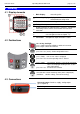
8 Output
The output can be used as serial interface (for USB 5100 interface converter).
If the output is not needed, it is strongly recommended to deactivate it (Out oFF) to lower power
consumption. This increases battery life time.
If the device is used together with interface adapter USB 5100 the device is supplied from the interface.
Pin assignment:
4: external supply +5V, 50 mA
3: GND
2: TxD/RxD (3.3V Logic)
1: not used
Only suitable adaptor cables are
permitted (accessories)!
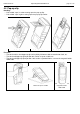
8.1 Interface
The device can be connected to a USB interface of a PC by the electrically isolated interface converter
USB 5100 (accessory). The data is transmitted binary-coded and protected against transmission errors by
complex safety mechanism (CRC).
The following standard software packages are available:
GSOFT3050: Operating and evaluation software for the integrated logger function
EBS20M / -60M: 20-/60-channel software for measuring value display
GMHKonfig: Configuration Software (for free on internet)
In case you want to develop your own software we offer a GMH3000-development package including:
a universally applicable Windows functions library ('GMH3x32e.DLL') with documentation, can be used
by all „established‟ programming languages, suitable for:
Windows XP™, Windows Vista™, Windows 7™
Programming examples Visual Basic 4.0™, Delphi 1.0™, Testpoint™ etc.
The device has 3 channels:
- Channel 1: current measuring value (sensor 1) and base address
- Channel 2: min peak
- Channel 3: max peak
The measuring-/ alarm- and display range values read back from the interface are always in
the selected measurement unit (mbar, bar...)!
9 Input Adjustment
The zero point and slope of each measuring inputs can be adjusted with the parameters offset (“OFFS”) and
scale (“SCAL”).
A reasonable adjustment presumes reliable references (e.g. ice water, controlled precision water bath, etc.).
If the inputs are adjusted (i.e. offset and scale are different from default settings) the device will shortly
display “Corr” after turned on.
Default setting for offset and scale are „off‟ = 0.0, i.e. inputs are not changed.
Zero point correction:
Displayed value = measured value – OFFS
Zero point and slope correction:
Displayed value = (measured value – OFFS) * (1 + SCAL / 100 )