
Owners Manual


12
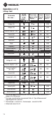
Settings Table
To measure
this value …
Set the
selector
to this
symbol…
These icons
appear on the
display …
Connect
the red
lead to…
Connect
the black
lead to …
ALL MODELS
Voltage (AC)
V
+ COM
Voltage (DC)
V
+ COM
Current, AmpTip™ (AC)
A
N/A N/A
Current (AC)
A
N/A N/A
Continuity
Ω
+ COM
Resistance
Ω kΩ
+ COM
Diode
V
+ COM
Frequency
Hz Hz
+ COM
Electric Field (EF)*
EF EF
N/A COM
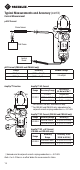
CM-860, CM-960, CMH-600, and CMI-600 Only
Capacitance**
µF
+ COM
CM-960 and CMI-600 Only
Voltage (AC + DC) + COM
Current, AmpTip™ (DC)
A
N/A N/A
Current, AmpTip™
(AC + DC)
A
N/A N/A
Current (DC)
A
N/A N/A
Current (AC + DC)
A
N/A N/A
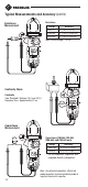
CMH-600 and CMI-600 Only
Temperature
Temp C or F
***
Current (µDC)
µA
+ COM
Phase Rotation† + COM
Motor Rotation† + COM
* Use the top side of the stationary jaw, or for more precise measurements use a
probe in the COM terminal.
** Discharge capacitor before measurement. Refer to “Typical Measurements”
regarding polarized capacitors.
*** Thermocouple + connects to +, thermocouple – connects to COM.
† Yellow lead connects to L3.
Operation (cont’d)