
User guide

21
Model VSU Make-Up Air
®
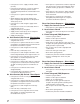
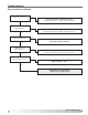
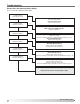
Direct Gas Burner Sequence - Pilot Ignition
1. Supply Fan Contact Closed
• Power passes to the supply fan and heat switch
2. Heat Contact Closed
• Power passes to the heat relay then to the Flame
Safeguard
3. Flame Safeguard (FSG) Sequence
• Checks for proper airflow
• Verifies no flame present at burner
• Initiates 10 second prepurge
• Sends power to open pilot gas valve (V1) and
energizes the spark generator (SG) (clicking of the
spark generator may be heard)
• Tries for up to 10 seconds to light pilot and
confirm flame
• Powers the main gas valves open
• Shuts down spark generator
• Continuously monitors the flame and airflow
• Performs self-diagnostic check every five
seconds.
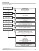
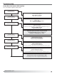
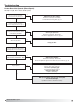
Direct Gas Burner Sequence - Direct Spark
1. Supply Fan Contact Closed
• Power passes to the supply fan and heat switch
2. Heat Contact Closed
• Power passes to the heat relay then to the Flame
Safeguard
3. Flame Safeguard (FSG) Sequence
• Checks for proper airflow
• Verifies no flame present at burner
• Initiates 15 second prepurge
• Sends power to open gas valve (V2) and
energizes the spark generator (clicking of the
spark generator may be heard)
• Tries for up to 10 seconds to light and confirm
flame
• Shuts down spark generator
• Continuously monitors the flame and airflow
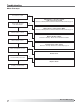
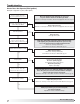
• Power passes to N.C. supply overload contact
(ST1 OL)
• Power passes through N.C. contact on optional
freeze protection timer (RT4) which remains
closed if the temperature has remained above the
set point
• Power passes to optional inlet damper which
opens
• When damper is fully opened, damper relay
(D1) is energized and optional N.O. damper limit
switch (DL1) closes
• Power passes to and energizes supply starter
relay (RF)
• Power passes to N.O. fan contact (RF), which is
energized and closed
• Supply starter (ST1) is energized
• Supply starter contact (ST1) closes and power
reaches and energizes supply fan
• Supply fan (M1) starts
3a. Heat Contact (S4) Closed - Pilot Ignition
• Power passes to N.O. fan relay (RF) which is
energized and closed
• Power passes to optional inlet air sensor contact
(TS4) which is energized and closed if the inlet air
temperature is below the set point
• Power passes to and energizes the heat relay
(RH)
• N.O. heat relay contact (RH) closes
• Power passes to and energizes terminal 5 of the
Flame Safeguard (FSG). Power light on FSG is on.
• Power passes to N.C. high limit control contact
(HLC1) which is closed if temperature has
remained below set point
• Power passes to optional N.O. and N.C. high and
low gas pressure contacts (PS4 and PS3), which
are both closed if gas pressure is within the set
range
• Power passes to terminal 6 of the Flame
Safeguard (FSG)
• Power begins direct gas burner sequence
(see Direct Gas Burner Sequence)
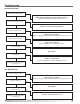
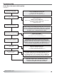
3b. Heat Contact (S4) Closed - Direct Spark
• Power passes to N.O. fan relay (RF) which is
energized and closed
• Power passes to optional inlet air sensor contact
(TS4) which is energized and closed if the inlet air
temperature is below the set point
• Power passes to and energizes the heat relay
(RH)
• N.O. heat relay contact (RH) closes
• Power passes to N.C. high limit control contact
(HLC1) which is closed if temperature has
remained below set point
• Power passes to optional N.O. and N.C. high and
low gas pressure contacts (PS4 and PS3), which
are both closed if gas pressure is within the set
range
• Power passes to N.O. and N.C. airflow switches
(PS2) which are closed if there is proper airflow
across the burner
• Power passes to terminal TH on the Flame
Safeguard (FSG) which begins it’s sequence
(see Direct Gas Burner Sequence)