
Corp. Fan User Manual

69
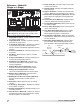
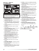
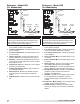
1. Low Voltage Transformer - Provides low voltage
to the ignition controller and amplifier.
2. Control Terminal Block - Provides wiring access
to heat controls.
3. Control Terminal Block - Provides wiring access
to heat controls.
4. Ignition Controller - Controls the ignition of the
furnace. Maintains safe operation of the furnace.
5. Amplifier - Controls the modulating valve based
on the input from the temperature selector and the
discharge air sensor.
6. Temperature Selector - Allows the user to adjust
discharge air temperature.
7. Combustion Blower Contact - Passes power to
the combustion blower.
8. Airflow Switch - Monitors the airflow inside the
heat exchanger to ensure proper combustion
airflow.
9. High Fire Relay - Allows furnace to ignite on high
fire.
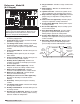
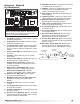
1. Low Voltage Transformer - Provides low voltage
to the ignition controller.
2. Low Voltage Transformer - Provides low voltage
to the 4:1 electronic modulation controller.
3. Low Voltage Transformer - Provides low voltage
to the amplifier.
4. Control Terminal Block - Provides wiring access
to controls.
5. Control Terminal Block - Provides wiring access
to controls.
6. Input Converter - Receives and converts signal
from Building Management System (BMS).
7. Ignition Controllers - Controls the ignition of the
furnace. Maintains safe operation of the furnace.
8. Modulation Controller - Provides 4:1 modulation
turndown control of furnace based on the
discharge air temperature.
9. Amplifier - Controls the modulating valve based
on the input from the modulation controller
settings and discharge air temperature sensor
reading.
10. Combustion Blower Relay - Passes power to the
variable speed combustion blower.
11. Airflow Switches - Monitors the airflow inside
the heat exchanger to ensure proper combustion
airflow.
Reference - Model IGX
(2:1 Modulation)
NOTE
This is a typical furnace control center, the control
center in your unit may be different. Reference the
ladder diagram on the inside of the control center
door for a unit specific wiring diagram.
2
3
1
4
5
6
7
8
9
NOTE
This is a typical furnace control center, the control
center in your unit may be different. Reference the
ladder diagram on the inside of the control center
door for a unit specific wiring diagram.
Reference - Model IGX
(4:1 Modulation)
5
1 2
3
4
7
8
9
6
10
11
11
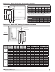
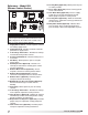
Manifold
Gas Pressure
Test Port
3/4 inch Gas Supply
Connection
Staged
Gas Valve
Modulating
Gas Valve
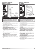
Manifold
Gas Pressure
Test Port
3/4 inch Gas Supply
Connection
Staged
Gas Valve
Modulating
Gas Valve
®
Model IG / IGX Make-Up Air