
Corp. Fan User Manual

10
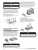
NOTE
Vent piping is supplied by others and not supplied
by manufacturer.
Installation of Concentric Venting
(General)
Concentric venting allows the exhaust pipe and
combustion air pipe to pass through a single hole in
the roof or wall of the building. A concentric venting
adapter (CVA) is required for concentric venting.
The concentric venting adapter is designed for indoor
installations and should never be installed on the
exterior of the building.
The exhaust pipe must terminate with the vent
terminal. For horizontal venting, the combustion air
pipe must terminate with the combustion air guard.
For vertical venting, the combustion air pipe must
terminate with the inlet terminal. Depending on what
was ordered, one of these vent terminals will be
provided in the optional venting kit along with the
concentric venting adapter (CVA).
If venting vertically through the roof, refer to the
vertical concentric venting instructions. If venting
horizontally through the wall, refer to the horizontal
concentric venting instructions.
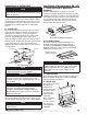
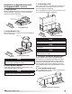
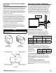
Concentric Venting – Horizontal
Refer to the diagram below for venting on horizontal
concentric systems. Maintain at least 12 inches from
the combustion air inlet guard to the exhaust vent
terminal (Dim. B). To prevent water from running
into the combustion air pipe and to allow for easy
installation of the combustion air inlet guard, the
combustion air pipe must terminate at least 2 inches
from the exterior surface of the outside wall (Dim. A).
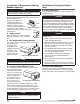
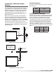
ÿ6 +/- 1/16COLLAR
ÿ4.00 COLLAR WITH
CRIMPED END
(ÿ3 7/8 +/- 1/16
AFTER CRIMPING)
BACK VIEW
CVA-4
4-inch Concentric
Venting Adapter
ÿ6 COLLAR WITH CRIMPED
END (ÿ5 7/8+/- 1/16 AFTER
CRIMPING)
BACK VIEW
CVA-6
6-inch Concentric
Venting Adapter
Top View
ÿ6 COLLAR WITH CRIMPED
END (ÿ5 7/8+/- 1/16 AFTER
CRIMPING)
BACK VIEW
Exhaust Connection
Concentric Side
Combustion Air Connection
Concentric Side
Exhaust Connection
Non-Concentric Side
Combustion Air Connection
Non-Concentric Side
CVA
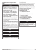
Vent Connection Diameter
Vent terminals must be used (one vent terminal
included with each furnace). Construct the vent
system as shown in the drawings and refer to the
table for the correct vent connection diameters.
Vent Length
Refer to table for minimum and maximum vent
lengths. The total equivalent vent length must include
elbows. The equivalent length of a 4 inch elbow is
6feet and the
equivalent length
of a 6inch elbow
is 10feet.
1. Determine Venting Location
Determine the location of the concentric venting
adapter (CVA) based on any clearances that must
be maintained (follow all codes referenced in these
instructions).
2. Attach Mounting Brackets
Attach field-supplied, corrosion resistant mounting
brackets to the CVA using corrosion resistant sheet
metal screws.
Vent
Length
Minimum
(feet)
Maximum
(feet)
Horizontal
5 70
Non-Concentric Vent
Connection Diameter
Concentric Vent
Connection Diameter
Furnace
Size (MBH)
Exhaust
(inches)
Combustion Air
(inches)
Exhaust
(inches)
Combustion Air
(inches)
75-175
4 4 4 6
200-400
6 6 6 8
A = 2 inch minimum
B = 12 inch minimum
Pitch vent pipe downward
from furnace 1/4 inch per foot
Mounting
Bracket
Mounting
Bracket
Exhaust
Vent
Terminal
EXHAUST
COMBUSTION AIR
Exterior
Wall
B A
Combustion
Air Inlet Guard
®
Model IG / IGX Make-Up Air