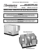
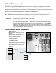
READ AND SAVE THESE INSTRUCTIONS ® PART #461248 HEAT RECOVERY UNIT WITH EVAPORATIVE COOLING Models: HRE-20, 45, 55, & 90 INSTALLATION, OPERATION AND MAINTENANCE MANUAL **WARNING** DISCONNECT AND SECURE TO THE "OFF" POSITION ALL ELECTRICAL POWER TO THE UNITS PRIOR TO INSPECTION OR SERVICING. FAILURE TO COMPLY WITH THIS SAFETY PRECAUTION COULD RESULT IN SERIOUS INJURY OR DEATH. **IMPORTANT** ALL FACTORY PROVIDED LIFTING LUGS MUST BE USED WHEN LIFTING THE UNITS.
TABLE OF CONTENTS Storage . . . . . . . . . . . . . . . . . . . . . . . . . . 2 General . . . . . . . . . . . . . . . . . . . . . . . . . . 2 Installation . . . . . . . . . . . . . . . . . . . . . . . 3 Lifting . . . . . . . . . . . . . . . . . . . . . . . . . .3 Unit Weights . . . . . . . . . . . . . . . . . . . . .3 Recommended Roof Openings . . . . . . .3 Roof Curb Mounting . . . . . . . . . . . . . . .4 Duct Work Connections . . . . . . . . . . . . 4 Weatherhoods . . . . . . . . . . . . . . . . . . .
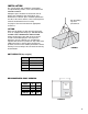
INSTALLATION The system design and installation should follow accepted industry practice, such as described in the ASHRAE Handbook. Adequate space should be left around the unit for piping coils and drains, filter replacement, and maintenance. Sufficient space should be provided on the side of the unit for routine service and component removal should that become necessary. Lift using lifting lugs and spreader bar See pages 6 and 7 for more detail on appropriate clearances.
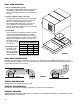
ROOF CURB MOUNTING 1. Factory Supplied Roof Curbs Roof curbs are Model GKD, which are shipped in a knockdown kit and require field assembly (by others). Assembly instructions are included with the curb. 2. Cut Roof Opening and Locate Curb Layout the unit roof opening such that the supply discharge & exhaust inlet of the unit will line up with the corresponding ductwork (refer to Recommended Roof Openings on page 3). Be sure to allow for the recommended service clearances.
INSTALLATION (continued) ELECTRICAL CONNECTIONS The electrical supply must be compatible with that shown on the nameplate: voltage, phase, and amperage capacity. The electrical supply line must be properly fused and conform to local and national electrical codes. All internal electrical components are pre-wired at the factory. Field electrical connections only need to be made inside the unit to the main disconnect (See FIGURE 5, Item #1) and the 24 volt control circuit (See FIGURE 5, Item #7).
SERVICE CLEARANCES / ACCESS PANEL LOCATIONS for Model HRE HRE-20, 45, 55, and 90 units require minimum clearances for access on all sides for routine maintenance. Filter replacement, drain pan inspection and cleaning, energy wheel cassette inspection, fan bearing lubrication and belt adjustment, are examples of routine maintenance that must be performed.
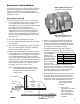
Evaporative Cooling Modules Indirect Evaporative Cooler It is important to mount the heat recovery unit level to ensure proper operation and water drainage. Piping should be of adequate size to provide sufficient supply of water to meet the maximum demand of the evaporative coolers. (Exhaust/Scavenger Airstream) Evap Module Start-Up 1.
WATER CONTROL OPTIONS FOR EVAPORATIVE COOLING Auto Drain and Fill with Freeze Protection This system will automatically drain the sump tank and fill it with fresh water at the field adjustable intervals, typically once every 24 hours. This flushes mineral build-up and debris from the tank to promote low maintenance and increase media pad life.
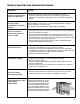
TROUBLE SHOOTING FOR EVAPORATIVE MODULE Symptom Solution Insufficient water volume or recirculation pump not operating A. Check water level in base pan. The level should be at 2 inches. B. Check the pump filter at the inlet. Clean the filter if clogged or dirty. C. If pump is not operating, check wiring for loose connections and proper voltage. Irregular water distribution on cooling media Water distribution header, orifices or media partially blocked or plugged. Remove evaporative cooler from unit.
EVAPORATIVE COOLING MAINTENANCE Regularly scheduled maintenance is the key to peak performance, minimized cost, and extended life of the evaporative cooler. The following is a checklist of items that need to be looked at on a regular basis. 1. 2. 7. The media should be checked for mineral and foreign material deposits that have built up. If these items are left on the media, the life and performance of the unit will be greatly reduced.
WATER COIL APPLICATION RECOMMENDATIONS Factory installed heating components are mounted down stream of the energy wheel (and direct evaporative cooler if supplied) on the supply air side of the unit. See FIGURE 10 for coil connection location. Coil connections are located external to the unit as shown. Coil connections that are not external have been ordered from the factory with interior or exhaust air stream coil connections. Water coil connections FIGURE 10 1.
ELECTRIC HEATER APPLICATION/OPERATION Factory installed electric heaters can be provided for preheat and/or post-heat (see FIGURE 11). An electric preheater warms the outdoor air prior to the energy recovery wheel to prevent frosting on the wheel. An electric post-heater warms the air leaving the energy recovery wheel to a user specified discharge temperature. Electric heaters are available in 208, 230, or 460 Vac (refer to heater nameplate for voltage).
FROST CONTROL APPLICATION/OPERATION When outdoor air temperatures are extremely cold, moisture condensation and frosting on the energy recovery wheel is possible. Frost control is an optional feature that will prevent wheel frosting.
ECONOMIZER APPLICATION/OPERATION The energy recovery wheel may be de-energized for the purpose of providing economizer (free cooling) operation. This can be achieved with a signal from a Temperature or Enthalpy sensor mounted in the supply air inlet compartment (see FIGURE 13). This Primary sensor will de-energize the energy wheel when the outdoor air temperature (factory default is 65°F) or enthalpy (factory default is the ‘D’ setting) is below the field adjustable set point.
START UP CHECKS **WARNING** DO NOT OPERATE ENERGY RECOVERY VENTILATOR WITHOUT THE FILTERS AND BIRDSCREENS INSTALLED. THEY PREVENT THE ENTRY OF FOREIGN OBJECTS SUCH AS LEAVES, BIRDS, ETC. DO NOT REMOVE ACCESS PANELS OR OTHER UNIT COMPONENTS WHILE STANDING ON A LADDER OR OTHER UNSTEADY BASE. ACCESS PANELS AND UNIT COMPONENTS ARE HEAVY AND SERIOUS INJURY MAY OCCUR.
Check pulleys and belts for proper alignment to avoid unnecessary belt wear, noise, vibration and power loss. Motor and drive shafts must be parallel and pulleys in line (see FIGURE 16). FAN RPM The adjustable motor pulley is preset at the factory to the customer specified RPM. Fan speed can be increased or decreased by adjusting the pitch diameter of the motor pulley. Multi-groove variable pitch pulleys must be adjusted an equal number of turns open or closed.
ROUTINE MAINTENANCE CAUTION: See **WARNING** on Page 1 and 15 Once the unit has been put into operation, a periodic maintenance program should be set up to preserve the reliability and performance. Items to be included in this program are: • • • • • • • BELTS MOTORS WHEEL AND FASTENERS VIBRATION FILTER MAINTENANCE COIL MAINTENANCE ENERGY WHEEL CASSETTE FAN BELTS Belts tend to stretch after a period of time. They should be periodically checked for tension and wear.
VIBRATION Excessive vibration maybe experienced during initial start-up. Left unchecked, excessive vibration can cause a multitude of problems, including structural and/or component failure. The most common sources of vibration are listed below. Many of these conditions can be discovered by careful observation. Refer to the troubleshooting section of this manual for corrective actions.
WATER COIL MAINTENANCE CAUTION: See **WARNING** on Page 1 and 15 FILTERS Filters upstream of the coil should be checked regularly. If the filters are dirty, they should be cleaned or replaced. It is important that the coils stay clean to maintain desired airflow. See page 18 for more information on filter maintenance. COIL MAINTENANCE 1. Coils must be clean to obtain maximum performance. Check once a year under normal operating conditions and, if dirty, brush or vacuum clean.
ROUTINE ENERGY RECOVERY WHEEL MAINTENANCE CAUTION: See **WARNING** on Page 1 and 15 MAINTENANCE OF THE ENERGY RECOVERY WHEEL Annual inspection of the energy recovery wheel is recommended. Units ventilating smoking lounges and other non-clean air spaces should have energy recovery wheel inspections more often based upon need. Inspections for smoke ventilation applications are recommended bimonthly to quarterly until a regular schedule can be established.
REMOVING THE ENERGY RECOVERY WHEEL SEGMENTS Model HRE-20, 45, 55, & 90 Steel retainers are located on the inside of the wheel rim (FIGURE 22). Push the retainer toward center of wheel, then lift up and away to release segments (FIGURE 23). Bracket Segment Retainer Lift Away From Segment CatchSegment Retainer Inside of Wheel Rim Spoke Push Toward Center Cen ter of W hee l FIGURE 22 IMPORTANT! PLACE RETAINERS BACK IN THE ORIGINAL POSITION BEFORE ROTATING THE ENERGY RECOVERY WHEEL.
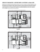
PARTS LIST 11 3 6 7 8 1 5 2 12 10 7 9 4 Model HRE (shown with indirect evaporative cooler, optional direct evaporative cooler, and indirect gas heater) 1. Supply blower - Forward curved fan - Adjustable motor mount for belt tensioning - Adjustable sheaves for speed control 2. Vibrations isolators (quantity 4 per blower) - Neoprene 3. Energy recovery wheel cassette 4. Removable energy recovery wheel segments 5. Optional supply weatherhood with 2 in. aluminum mesh filter 6.
Trouble Shooting Symptom Blower Fails to Operate Motor Starters “Chatter” or Do Not Pull In Motor Over Amps Low Airflow (cfm) Possible Cause Corrective Action Blown fuse or open circuit breaker. Replace fuse or reset circuit breaker and check amps. Defective motor or capacitor. Replace Motor starter overloaded. Reset starter and check amps. Electrical. Check for On/Off switches. Check for correct supply voltage. Drive. Check for broken or loose belts. Tighten loose pulleys.
Trouble Shooting Symptom Possible Cause Corrective Action One or Both Blowers Turn Off Intermittently and Back on After About 2 Minutes Blower fan motor overloads are tripping and auto-resetting. Decrease fan speed. Exhaust Only frost control sensors are tripping. Adjust frost temperature sensor set point as needed. Air seals are too tight. See Energy Recovery Wheel on page 16. “Economizer” sensors are operating. Adjust temperature or enthalpy set points as needed. No power to wheel motor.