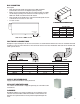
READ AND SAVE THESE INSTRUCTIONS PART #461248 HEAT RECOVERY UNIT WITH EVAPORATIVE COOLING ® Models: HRE-20, 45, 55, & 90 Installation, Operation and Maintenance Manual RECEIVING AND HANDLING The HRE is thoroughly inspected and test run at the factory. However, damage may occur during shipping and handling. Upon delivery, inspect the unit for both obvious and hidden damage. If damage is found, record all necessary information on the bill of lading and file a claim with the final carrier.
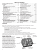
TABLE OF CONTENTS Storage and Basic Operation . . . . . . . . . . . . . 2 Installation . . . . . . . . . . . . . . . . . . . . . . . . . . . . . 3 Lifting . . . . . . . . . . . . . . . . . . . . . . . . . . . . . . . . . 3 Unit Weights & Recommended Roof Openings . . . . . . . . . . . . . . . . . . . . . . . . . . . . 3 Roof Curb Mounting . . . . . . . . . . . . . . . . . . . . .
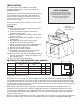
INSTALLATION The system design and installation should follow accepted industry practice, such as described in the ASHRAE Handbook. Safety Warning All factory provided lifting lugs must be used when lifting the units. Failure to comply with this safety precaution could result in property damage, serious injury, or death. Adequate space should be left around the unit for piping coils and drains, filter replacement, and maintenance.
ROOF CURB MOUNTING Rooftop units require curbs to be mounted first. The duct connections must be located so they will be clear of structural members of the building. Roof curb details, including duct location 1. Factory Supplied Roof Curbs dimensions, are available on HRE roof curb Roof curbs are Model GKD, which are shipped in a assembly instructions. knockdown kit (includes duct adapter) and require field assembly (by others). Assembly instructions are included with the curb. 2.
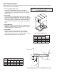
RAIL MOUNTING ion at ion at Rail Layout • Rails designed to handle the weight of the HRE should be positioned as shown on the diagram (rails by others). • Make sure that rail positioning does not interfere with the supply air discharge opening or the exhaust air intake opening on the HRE unit. Avoid area dimensioned “B” below • Rails should run the width of the unit and extend beyond the unit R t Tu rning R ot a minimum of 12 oinches on each side. Vanes • Set unit on rails.
ELECTRICAL INFORMATION The unit must be electrically grounded in accordance with the current National Electrical Code, ANSI/NFPA No. 70. In Canada, use current C.S.A. Standard C22.1, Canadian Electrical Code, Part 1. In addition, the installer should be aware of any local ordinances or electrical company requirements that might apply. System power wiring must be properly fused and conform to the local and national electrical codes.
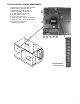
TYPICAL CONTROL CENTER COMPONENTS 1. Main Disconnect (non-fusible, lockable) 2. Motor Starter - Exhaust Air Fan 3. Motor Starter - Outdoor Air Fan 4. Motor Contactor - Energy Wheel 5. 24 VAC Control Transformer 6. 24 VAC Terminal strip 7. Fuses for blower motors 8. Motor Contactor - Indirect Evap Pump 9. Motor Contactor - Direct Evap Pump 10.
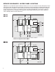
SERVICE CLEARANCES / access panel locations HRE-20 HRE-45 Access Panel HRE-20, 45, 55, and 90 units require minimum clearances for access on all sides for routine maintenance. Filter replacement, drain pan inspection and cleaning, energy wheel cassette inspection, fan bearing lubrication and belt adjustment, are examples of routine maintenance that must be performed.
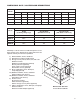
DIMENSIONAL DATA / ACCESS DOOR DESCRIPTIONS Model Exterior Dimensions A B C D E F G H I HRE-20 98 50 56 18 28.5 17 6 14.25 18 HRE-45 106 69 66 16 41 23.375 10.5 13.375 20 HRE-55 118 70 76 16 59.5 5.875 7.125 21.25 25 HRE-90 131 85 96 16 78 2.875 10 24.5 27 All dimensions shown are in inches. Overall Exterior Dimensions Model Width (including Lifting Lugs) Overall Width (with Exhaust Hood) Overall Length (with Outdoor Air Hood) HRE-20 59.
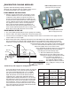
EVAPORATIVE COOLING MODULES Indirect Evaporative Cooler Mount the heat recovery unit level to ensure proper operation and water drainage. Piping should be of adequate size to provide sufficient supply of water to meet the maximum demand of the evaporative coolers. (Exhaust/Scavenger Airstream) EVAP MODULE INSTALLATION 1.
7. Verify that both airflow and system static pressure are in agreement with the specifications. If these conditions are met, check for water carry over from the discharge side of the media. If carry over is observed, check the distribution header for holes or tears and the water standoff tube for blockage. 8. After all final adjustments are made, remove the jumper wires, connect “call for cooling” signal, and replace all access panels. The unit is now ready for operation.
AUTO DRAIN AND FILL WITH FREEZE PROTECTION Water Control Options for Evaporative Cooling THE SYSTEM WILL AUTOMATICALLY DRAIN THE SUMP TANK AND FILL IT WITH FRESH WATER AT THE FIELD ADJUSTABLE INTERVALS, TYPICAL SETTINGS ARE t1 = 24HRS t2 = 10 MIN. WITH THE DIP SWITCH IN THE DOWN POSITION. THIS FLUSHES MINERAL BUILD-UP AND DEBRIS FROM THE TANK TO PROMOTE LOW MAINTENANCE AND INCREASE MEDIA PAD LIFE.
INCREASE MEDIA PAD LIFE. IN ADDITION, THE SYSTEM WILL PROTECT THE EVAPORATIVE COOLER FROM FREEZING BY DRAINING THE SUMP TANK AND SUPPLY LINE WHEN THE OUTSIDE TEMPERATURES FALL BELOW THE SET POINT OF THE OUTDOOR AIR SENSOR. TYPICALLY, THIS IS SET AT 45° TO 50° F. THE AUTO DRAIN AND FILL OUTDOOR AIR SENSOR SHOULD BE INSTALLED IN AN AREA THAT IS SHADED FROM DIRECT SUNLIGHT SO THE SENSOR PROBE WILL DETECT AN ACCURATE AIR TEMPERATURE.
DRAIN AND OVERFLOW CONNECTION LOCATIONS Connection Locations - in inches Model Outdoor Air Side Exhaust Side A B C D A B C D HRE-20 4.00 2.875 40.75 42.25 4.00 2.875 52.25 53.75 HRE-45 6.25 5.125 42.625 44.125 6.25 5.125 56.50 58.00 HRE-55 6.375 5.125 53.00 54.50 6.375 5.125 66.375 67.875 HRE-90 6.375 5.125 47.25 48.50 6.375 5.125 71.00 72.
Troubleshooting for evaporative module Symptom Solution A. Check water level in base pan. The Insufficient water volume or recirculation level should be at 1 inch. pump not operating B. Check the pump filter at the inlet. Clean the filter if clogged or dirty. C. If pump is not operating, check wiring for loose connections and proper voltage. D. Clogged or worn out pump. E. Clogged header. F.
Evaporative Cooling Maintenance Regularly scheduled maintenance is the key to peak performance, minimized cost, and extended life of the evaporative cooler. The following is a checklist of items that need to be looked at on a regular basis. 1. The media should be checked for mineral and foreign material deposits that have built up. If these items are left on the media, the life and performance of the unit will be greatly reduced. Also, there are risks of water carryover when this type of condition exists.
optional accessories Electric Heater Application/Operation Factory installed electric heaters can be provided for preheat and/or post-heat. An electric preheater warms the outdoor air prior to the energy recovery wheel to prevent frosting on the wheel. An electric post-heater warms the air leaving the energy recovery wheel to a user specified discharge temperature. Electric heaters are available in 208, 230, or 460 Vac (refer to heater nameplate for voltage).
optional accessories Frost Control Application/Operation Extremely cold outdoor air temperatures can cause moisture condensation and frosting on the energy recovery wheel. Frost control is an optional feature that will prevent/control wheel frosting.
optional accessories Economizer Application/Operation The energy recovery wheel operation can be altered to take advantage of economizer operation (free cooling). Two modes are available: 1) De-energizing the wheel or 2) Modulating the wheel. A field supplied call for cool (Y1) is required. De-energizing the wheel is accomplished with a signal from a Temperature or Enthalpy sensor mounted in the supply air inlet compartment.
optional accessories Variable Frequency Drives for Blowers Optional factory installed, wired, and programmed variable frequency drives (VFD) may have been provided for modulating or multi-speed control of the blowers. One VFD is provided for each blower (outdoor air and exhaust). The VFDs provided are either Yaskawa model E7 or model GPD305. Refer to the tables on the next page for factory settings and field wiring requirements.
optional accessories Factory Setpoints - MODULATING CONTROL (0-10 VDC) FOR FAN SPEED Variable frequency drives (VFD) for the blowers are factory setup to receive a 0-10 VDC signal wired in the field (refer to previous page for terminal locations). Most of the setpoints in the VFDs are factory defaults. There are a few, though, that are changed at Greenheck and are shown in the tables below. To gain access to change setpoints on the E7 drive, parameter A1-01 needs to be set at “2”.
optional accessories Wiring Diagram Following is an example of a typical wiring diagram located in the unit control center. This wiring diagram includes a legend highlighting which accessories were provided with the unit. Factory wiring and field wiring are also indicated.
optional accessories Rotation Sensor The rotation sensor monitors energy recovery wheel rotation. If the wheel should stop rotating, the sensor will close a set of contacts in the unit control center. Field wiring of a light (or other alarm) between terminals R & 12 in the unit control center will notify maintenance personnel when a failure has occurred (refer to Remote Panel Wiring Schematics section for wiring details).
optional accessories CO2 Sensor This accessory is often used to provide a modulating control signal to a variable frequency drive to raise and lower airflow in relationship to the CO2 levels in the space. This strategy is often referred to as Demand Control Ventilation and provides further energy savings to the system. Follow instructions supplied with sensor for installation and wiring details. Service Outlet 120 VAC GFCI service outlet ships loose for field installation.
OPTIONAL ACCESSORIES Remote Control Panel and Wiring Schematics The remote panel is a series of junction boxes ganged together and includes a stainless steel face plate. The remote panel is available with a number of different alarm lights and switches to control the unit. The remote panel ships loose and requires mounting and wiring in the field.
OPTIONAL ACCESSORIES Remote Panel Wiring Schematics Indicator Lights powered by the ER Unit R C Unit On/Off G Y1 Y2 W1 Frost Control Economizer Rotation Sensor 6 7 12 NC NC PS2 C PS3 C NO Supply Dirty Filter NO Exhaust Dirty Filter Dirty Filter Indicator (Power by Others) PS2 NC C NO Supply Dirty Filter NO Exhaust Dirty Filter PS3 NC Hot L1 Refer to Pressure Switch for voltage and load ratings.
OPTIONAL ACCESSORIES Remote Panel Wiring Schematics Heating/Cooling Switches and Night Setback Switch/Timer R C S1 S6 S7 S4 Unit On/Off G Econ/First Stage Cooling Y1 Second Stage Cooling Y2 Heat W1 6 Terminal Block in Unit Control Center 7 12 Night Setback Switch A3 S5 A3 Night Setback Timer 27
optional accessories Sensors Mounted by Factory Factory mounted temperature, pressure, and current sensors are available in the locations indicated on the unit diagram below. A list of available sensors is shown below. The specific sensors provided on a given unit are labeled in the unit control center on the terminal strip. Sensors are wired to the terminal strip to make it easy for the controls contractor to connect the Building Management System for monitoring purposes.
Start-Up Checklist for unit Safety Danger! Electric shock hazard. Can cause injury or death. Before attempting to perform any service or maintenance, turn the electrical power to unit to OFF at disconnect switch(es). Unit may have multiple power supplies. Safety Caution! Use caution when removing access panels or other unit components, especially while standing on a ladder or other potentially unsteady base. Access panels and unit components can be heavy and serious injury may occur.
Start-Up Checklist for unit Special Tools Required Voltage Meter (with wire probes) Amperage Meter Incline manometer or equivalent Tachometer Thermometer Start-Up Checklist The unit will be in operational mode during start-up. Use necessary precautions to avoid injury. All data must be collected while the unit is running. In order to measure volts & amps, the control center door must be open, and the unit energized using a crescent wrench to turn the disconnect handle.
OPTIONAL ACCESSORIES Checklist Refer to the respective sections in this Installation, Operation and Maintenance Manual for detailed information. Refer to wiring diagram in unit control center to determine what electrical accessories were provided.
unit start-up Refer to Parts List section for component locations. Fans (Forward Curved Type) The HRE Models contain a forward curved supply fan and a forward curved exhaust fan. These forward curved fans should be checked for free rotation. If any binding occurs, check for concealed damage and foreign objects in the fan housing. Be sure to check the belt drives per the start-up recommendations in the following section.
unit start-up Backward Inclined Rotation n Airflow R ota R ota tio Blower access is labeled on unit. Check for proper wheel rotation by momentarily n energizing the fan. Rotation is determined by viewing the wheel from the drive Airflow side and should match the rotation decal affixed to the fan housing (see Rotation Direction figures). If the wheel is rotating the wrong way, direction can be reversed by interchanging any two of the three electrical leads.
unit start-up Energy Recovery Wheel The HRE models contain a sensible energy recovery wheel. The wheels are inspected for proper mechanical operation at the factory. However, during shipping and handling, shifting can occur that may affect wheel operation. The wheel is accessible through the access door marked “Energy Wheel Cassette Access”. For the HRE-20 AND HRE-45 models, the wheel cassette slides out.
routine maintenance Safety Caution! Safety Danger! Use caution when removing access panels or other unit components, especially while standing on a ladder or other potentially unsteady base. Access panels and unit components can be heavy and serious injury may occur. Electric shock hazard. Can cause injury or death. Before attempting to perform any service or maintenance, turn the electrical power to unit to OFF at disconnect switch(es). Unit may have multiple power supplies.
routine maintenance Lubrication Check all moving components for proper lubrication. Apply lubrication where required. Any components showing excessive wear should be replaced to maintain the integrity of the unit and ensure proper operation. Dampers Check all dampers to ensure they open and close properly and without binding. Backdraft dampers can be checked by hand to determine if blades open and close freely. Apply power to motorized dampers to ensure the actuator opens and closes the damper as designed.
routine maintenance Bearings Most bearings are permanently lubricated and require not further lubrication under normal use. Normal use being considered -20ºF to 120ºF and in a relatively clean environment. Some bearings are re-lubricatable and will need to be regreased depending on fan use. Check your bearings for grease zert to find out what type of bearing you have. If your fan is not being operated under normal use, bearings should be checked monthly for lubrication.
routine maintenance Energy Recovery Wheel Maintenance Annual inspection of the energy recovery wheel is recommended. Units ventilating smoking lounges and other non-clean air spaces should have energy recovery wheel inspections more often based upon need. Inspections for smoke ventilation applications are recommended bimonthly to quarterly until a regular schedule can be established. ACCESSING ENERGY RECOVERY WHEEL The HRE units have one energy recovery wheel.
routine maintenance CLEANING THE ENERGY RECOVERY WHEEL If the wheel appears excessively dirty, it should be cleaned to ensure maximum operating efficiency. Only excessive buildup of foreign material needs to be removed. DISCOLORATION AND STAINING OF ENERGY RECOVERY WHEEL DOES NOT AFFECT ITS PERFORMANCE. Thoroughly spray wheel matrix with household cleaner such as Fantastic® or equivalent. Gently rinse with warm water and using a soft brush remove any heavier accumulation.
PARTS LIST 3 6 11 7 8 1 5 2 12 10 7 9 4 Model HRE (shown with indirect evaporative cooler, optional direct evaporative cooler, and indirect gas heater) 1. Supply blower - Forward curved fan - Adjustable motor mount for belt tensioning - Adjustable sheaves for speed control 2. Vibrations isolators (quantity 4 per blower) - Neoprene 3. Energy recovery wheel cassette 8.
SEQUENCE OF OPERATION Basic Unit The HRE units are pre-wired such that when a call for outside air is made (via field supplied 24 VAC control signal wired to unit control center), the supply fan, exhaust fan and energy wheel are energized and the motorized dampers open. The HRE units can be supplied with or without heating and cooling coils. For units with coils, controls can be supplied by Greenheck or by the controls contractor.
Troubleshooting Airflow Test and Balance Report The test and balance report (TAB) is utilized to determine whether the appropriate amount of outdoor air and exhaust air is being supplied and removed from a building, respectively. There are no set rules on what information must be included in a TAB report.
Troubleshooting Symptom Blower Fails to Operate Motor Starters ‘Chatter’ or Do Not Pull In Motor Over Amps Low Airflow (cfm) High Airflow (cfm) Possible Cause Corrective Action Blown fuse or open circuit breaker. Replace fuse or reset circuit breaker and check amps. Defective motor or capacitor. Replace. Motor starter overloaded. Reset starter and check amps. Electrical. Check for On/Off switches. Check for correct supply voltage. Drive. Check for broken or loose belts.
Troubleshooting Symptom Possible Cause Corrective Action One or Both Blowers Turn Off Intermittently and Back on After About 2 Minutes Blower fan motor overloads are tripping and auto-resetting. Decrease fan speed. Exhaust Only frost control sensors are tripping. Adjust frost temperature sensor set point as needed. Air seals are too tight. See Energy Recovery Wheel under Unit Start-Up section. ‘Economizer’ sensors are operating. Adjust temperature or enthalpy set points as needed.