FLOOR/CEILING OWNER’S MANUAL Models: Indoor Unit UMAT18HP230V1AF UMAT24HP230V1AF UMAT30HP230V1AF UMAT36HP230V1AF UMAT42HP230V1AF UMAT48HP230V1AF Outdoor Unit UMAT18HP230V1AO UMAT24HP230V1AO UMAT30HP230V1AO UMAT36HP230V1AO UMAT42HP230V1AO UMAT48HP230V1AO
Thank you for choosing a Floor /Ceiling Air Conditioning & Heating System. You can feel confident in your selection because the same pride in craftsmanship and engineering knowledge that goes into millions of other Gree installed products worldwide has gone into your unit. Please read this owner’s manual carefully before operation and retain it for future reference. Table of Contents Introduction . . . . . . . . . . . . . . . . . . . . . . . . . . . . . . . . . . . . . . . . . . . . . . . . .
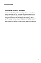
INTRODUCTION Superior Design for Superior Performance Gree’s Universal Floor/Ceiling indoor unit is designed to be suspended from a ceiling or mounted low on a wall. The slender and lightweight design is perfect for restaurants, light commercial applications, or wherever wall space is limited. Aesthetically pleasing to the eye, the Universal Floor/Ceiling unit is a great fit beneath windows, in hallways or in any public space requiring discreet, powerful climate control.
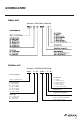
NOMENCLATURE Indoor unit Example: UMAT18HP230V1AF F Outdoor unit Example: UMAT18HP230V1AO UMAT 18 HP 230V 1 A O Series Designation UMAT – U-Match Series Cooling Capacity 18 - 18,000 BtuH 24 - 24,000 BtuH 30 - 30,000 BtuH 36 - 36,000 BtuH 42 - 42,000 BtuH 48 - 48,000 BtuH Product Type S - System O - Outdoor Units H - Indoor High Wall D - Indoor Duct C - Indoor Cassette F - Indoor Floor/Ceiling Revision Level Style/Color Designation Model Type AC - Cooling Only HP - Heat Pump HC - Heat/Cool Electric
SAFETY PRECAUTIONS Please read the following before operation. Recognize safety information. This is the safety-alert symbol. When you see this symbol on the unit and in instructions or manuals, be alert to the potential for personal injury. Understand these signal words: DANGER, WARNING, and CAUTION. These words are used with the safety-alert symbol. DANGER identifies the most serious hazards which will result in severe personal injury or death.
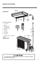
System Schematic Air Outlet Indoor Unit Air inlet System Combonents* 1. Front Cabinet 2. Air Inlet 3. Wired Controller (sold separately) 4. Remote Controller 5. Drain Pipe 6. Gas Pipe 7. Liquid Pipe 8. Service Cover 9. Front Panel Power Supply 2 1 3 4 * Not all items included in equipment purchase Air inlet Outdoor Unit Air outlet 9 8 7 6 5 CAUTION The refrigerant pipe, drain pipe and electrical wiring for this unit should be installed by a qualified HVAC professional only.
SYSTEM FUNCTIONS WHISPER QUIET Not only are the Gree systems energy efficient but they are quiet too. Wall mounted units operate with sound levels starting as low as 37 dB(A). MODERN APPEARANCE Designed to be a comfortable fit in virtually any living space. This slim compact cabinet sits inconspicuously on the wall or ceiling, and blends into most interior designs.
SYSTEM FUNCTIONS CONTROLLERS The unit comes with a factory supplied Wireless Remote Controller. A Gree Wired Tether Controller can be purchased separately for the Floor/Ceiling unit. NOTE: The controllers are mutually exclusive. They cannot be used at the same time. IR WIRELESS REMOTE CONTROLLER The Gree multi-functional infrared hand held wireless controller is sleek, ergonomically designed, easy to use and has a large LCD display (not back lighted).
SYSTEM FUNCTIONS TURBO MODE Use Turbo Mode for situations where you wish to achieve the desired room temperature in the shortest possible time. This mode runs the unit at ultra high speeds for quickest results. MODE BUTTON The unit can be set to five different operating modes: HEAT, COOL, DRY, FAN ONLY and AUTO. NOTE: AUTO MODE has fixed setpoints of 68° F heating and 77° F cooling, which are not adjustable.
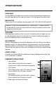
OPERATION OF WIRELESS REMOTE CONTROLLER Remote Controller 1 Part Name 2 3 4 5 6 7 8 9 11 12 14 15 10 13 1 Signal Transmitter 2 ON/OFF Button 3 Mode Button 4 – Button 5 + Button 6 Fan Button 7 Swing Button 8 Clock Button 9 Timer ON Button 10 X-Fan Button 11 Temp Button 12 Timer OFF Button 13 Turbo Button 14 Sleep Button 15 Light Button INTRODUCTION FOR ICONS ON DISPLAY SCREEN Set Fan Speed Operation Mode Auto Mode X-Fan Mode Cool Mode Dry Mode Set Temperature Fan Mode Turbo Mode Timer On Se
OPERATION OF WIRELESS REMOTE CONTROLLER REMOTE CONTROLLER OPERATIONS The wireless remote controller is sleek, versatile and allows you to change room temperatures and functions on your U-Match Floor/Ceiling system from the palm of your hand. The large LCD display and buttons make it easy-to-understand and easy-to-use. The remote controller is set from factory to display temperatures in°F. If °C is desired, turn the remote OFF and then press “MODE“ and “––” buttons on the remote simultaneously.
OPERATION OF WIRELESS REMOTE CONTROLLER MODE BUTTON Use the “MODE” button to select one of the available modes. The selected mode will be displayed on the remote controller and the appropriate icon will be displayed. AUTO – Unit will automatically select heating or cooling to maintain room temperature between 68°F and 77°F. The remote controller will display the Auto Mode icon with no setpoint. The front panel display will show "77.
OPERATION OF WIRELESS REMOTE CONTROLLER TIMER ON MODE The Floor/Ceiling unit can be programmed to automatically turn ON after a selected time period. With the unit in OFF mode, press TIMER button to activate the TIMER mode, and the ON/OFF icon will begin blinking. Press + or - button to select a time setting from 0.5 to 24 hours. Press once for slow adjustment and hold down for fast adjustment. Press TIMER button to confirm settings, and icon will stop blinking.
OPERATION OF WIRELESS REMOTE CONTROLLER X-FAN MODE When operating in humid areas, the unit has a DRY COIL function called X-Fan that will allow the indoor fan to run for a pre-determined amount of time after the unit is turned off (cooling or dry modes) to ensure that additional moisture is removed from coil. Push the “X-FAN” button to enable this feature. The X-FAN icon will be displayed on remote controller. To deactivate this feature, push the “X-FAN” button again.
OPERATION OF WIRELESS REMOTE CONTROLLER CLOCK BUTTON Press the CLOCK button to enter Clock Setup Mode. The clock icon will begin flashing. Set the clock by pressing the + or - buttons. Press once for slow adjustment; press and hold down for fast adjustment. When finished, press the CLOCK button to save your clock settings. This is the current time, not the timer setting. NOTE: Clock time adopts 24-hour mode. A 12-hour format is not available.
CARE AND CLEANING WARNING CAUTION WARNING WARNING Take notice of the following items before cleaning your air conditioning unit. • To avoid electric shock or injury, do not attempt to clean the unit unless both the indoor and outdoor units have been turned off and disconnected from the main power supply. • Do not wash the unit with water; this may cause an electric shock. NOTE: Do not use bleach, abrasives or water above 113°F (45°C) as it may cause discoloration or damage to the surface of the unit.
TROUBLESHOOTING PROBLEM CAUSE/SOLUTION System does not restart. Cause: The system has a built-in three-minute delay to prevent short and/or rapid cycling of the compressor. Solution: Wait three minutes for the protection delay to expire. Indoor unit emits unpleasant odor when started Cause: Typically unpleasant odors are the result of mold or mildew forming on the coil surfaces or the air filter. Solution: Wash indoor air filter in warm water with mild cleaner.
TROUBLESHOOTING PROBLEM CAUSE/SOLUTION Water leaking from the indoor unit into the room. Cause: While it is normal for the system to generate condensate water in cooling mode, it is designed to drain this water via a condensate drain system Solution: If water is leaking into the room, it may indicate one of the following. • The indoor unit is not level right to left. Level indoor unit. • The condensate drain pipe is restricted or plugged.
DIAGNOSTIC CODES The U-Match System has on board diagnostics. The indoor unit and Tether Controller will display error codes. The following is a summary of the codes with explanation: Error Codes No. 1 2 3 4 5 6 Error Code E1 E2 E3 Malfunction Name Origin of Malfunction Description High Pressure Protection High Pressure Switch If outdoor unit detects the high pressure switch is cut off for 3-sec successively, high pressure protection will occur.
DIAGNOSTIC CODES Error Codes No. Error Code Malfunction Name Origin of Malfunction 7 E9 Condensate Overflow Protection Overflow Switch If indoor unit detects the condensate overflow switch warning for 8-sec successively, the system will enter condensate overflow protection. The unit will shut off and will not recover automatically. Switch unit off and then switch it on to eliminate this malfunction.
DIAGNOSTIC CODES Error Codes No. Error Code Malfunction Name Origin of Malfunction Description 14 ee Outdoor Drive Memory Chip Malfunction Outdoor Drive Board If the memory chip of outdoor drive circuit board fails, the unit will not start. The unit will not recover automatically. If thermo junction cannot be eliminated after switching off the unit and then energizing the unit several times, replace the outdoor drive circuit board.
ENERGY SAVING TIPS 1. Reduce room setpoint at night: During the nighttime hours you don't require the same level of conscious cooling or heating. Try using Sleep Mode to gradually relax room temperature and allow the unit to run less and save energy. 2. Curtains and shades: In the summer, it is recommended to block the effects of the sun. Close window curtains and shades on the south and west side of your home to help block solar heat. In winter, the sun is your friend.
GREE ELECTRIC APPLIANCES, INC. www.greecomfort.com LIMITED WARRANTY GREE distributor (hereinafter “Company”) warrants this product against failure due to defect in materials or workmanship under normal use and maintenance as follows. All warranty periods begin on the date of original installation. If the date cannot be verified, the warranty period begins one hundred twenty (120) days from date of manufacture.