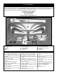
™ INSTRUCTION MANUAL A. R. F. Almost Ready to Fly Wingspan: 65 in [1651mm] Wing Area: 1072 sq in [69 dm2] Weight: 7 lbs - 7 lbs 6 oz [3175 - 3345g] Wing Loading: 15 - 15.9 oz/sq ft [46 - 48 g/dm2] Length: 69.5 in [1765mm] Engine: .61 - .91 cu in [10 - 15cc] two-stroke, .70 - .91 cu in [11 - 15cc] four-stroke WARRANTY Great Planes® Model Manufacturing Co. guarantees this kit to be free from defects in both material and workmanship at the date of purchase.
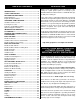
TABLE OF CONTENTS INTRODUCTION Whether you're just learning to do basic aerobatics or are looking for a quick practice plane as a backup to your $10,000 Unlimited aerobatic machine, U-CAN-DO 3D is just the bird you're looking for. INTRODUCTION ................................................................2 SAFETY PRECAUTIONS ..................................................2 DECISIONS YOU MUST MAKE ........................................3 Radio Equipment................................................
7. If you are not already an experienced R/C pilot, you should fly the model only with the help of a competent, experienced R/C pilot. Radio Equipment 4+ channel radio with 6 standard-sized servos as noted below. Note that a 6+ channel, fully computerized radio system is highly recommended for maximum flexibility and performance. 8. WARNING: The cowl and wheel pants included in this kit are made of fiberglass, the fibers of which may cause eye, skin and respiratory tract irritation.
❏ ❏ Covering Accessories ❏ ❏ ❏ Dead Center™ Engine Mount Hole Locator (GPMR8130) Great Planes AccuThrow™ Deflection Gauge (for measuring control throws, GPMR2405) 21st Century® sealing iron (COVR2700) 21st Century trim seal iron (COVR2750) 21st Century iron cover (COVR2702) IMPORTANT BUILDING NOTES • There are two types of screws used in this kit: Adhesives and Building Supplies Sheet metal screws are designated by a number and a length.
KIT CONTENTS Before starting to build, use the Kit Contents list to take an inventory of this kit to make sure it is complete and inspect the parts to make sure they are of acceptable quality. If any parts are missing or are not of acceptable quality, or if you need assistance with assembly, contact Great Planes Product Support. When reporting defective or missing parts, use the part names exactly as they are written in the Kit Contents list on this page.
ORDERING REPLACEMENT PARTS To order replacement parts for the Great Planes U-CAN-DO 3D ARF, use the order numbers in the Replacement Parts List that follows. Replacement parts are available only as listed. Not all parts are available separately (an aileron cannot be purchased separately, but is only available with the wing kit). Replacement parts are not available from Product Support, but can be purchased from hobby shops or mail order/Internet order firms.
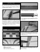
PREPARATIONS ❏ 1. If you have not yet done so already, remove the major parts of the kit from the box (wings, fuse, wheel pants, cowl, tail parts, etc.) and inspect them for damage. If any parts are damaged or missing, contact Product Support at the address or telephone number on page 5. ❏ 2. Use your sanding bar to round one end of each of the 5/16" x 1-3/4" [8 x 70mm] wing dowels. Use epoxy to glue the two wing dowels into the wing, with the non-rounded end in the wing. 1" 1" 3/4" ❏ 3.
❏ 6. Separate the ailerons from the wing and take out all the hinges. ❏ 10. Apply six drops of thin CA to the top and bottom of each hinge. Do not use CA accelerator. After the CA has fully hardened, test the hinges by pulling on the ailerons. ❏ 7. Drill a 3/32" [2.4mm] hole, 1/2" [13mm] deep at the marks you made in the center of each hinge slot. This space will allow the CA to “wick” in. Follow with a #11 blade to clean out the slots. Hint: If available, use a high-speed rotary tool to drill the holes.
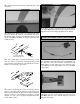
❏ ❏ 3. Pull the center of the string out of the servo hole in the wing. It might take a little fishing to get it out. Take your time. Use the string to pull the servo wire through the wing, being careful to not pull the string loose from the other end taped in the wing. Fit the servo in the wing. Correct Incorrect ❏❏ 6. Center a control horn on the mark you made. Drill two 1/16" [1.6mm] holes through the aileron for mounting the control horn.
❏ 12. Slide a silicone retainer over the two servo wires so they won’t fall back into the wing. Mount the Wing to the Fuselage ❏ 1. Mount the wing to the fuse with the two 1/4-20 x 2" [51mm] nylon bolts. ❏ ❏ 9. Attach the clevis with pushrod to the outer hole of the control horn. Hold the aileron straight with the wing and mark the pushrod where it crosses the servo arm. Bend the pushrod 90 degrees away from the wing on the mark you made. 1/16" Servo Arm Faslink Pushrod Wire ❏ 2.
BUILD THE FUSELAGE Mount the Stab and Fin ❏ 4. Use a #11 blade to remove the false fin from the fin slot. Note: It may be necessary to pry up slightly on the front of the fin fillet to remove it. ❏ 1. Attach the elevators to the stab with the same hinging technique used for the ailerons. ❏ 5. Fit the fin in place and mark the covering on the fin where it contacts the fuse. ❏ 2. Using a 7/64" hex wrench, remove the two 6-32 x 3/4" [19mm] socket head cap screws from the stab fillet. ❏ 6.
How to cut covering from balsa. To avoid cutting into the balsa, use a soldering iron instead of a hobby knife to cut the covering. The tip of the soldering iron doesn't have to be sharp, but a fine tip does work best. Allow the iron to heat fully. Use a straightedge to guide the soldering iron at a rate that will just melt the covering and not burn into the wood. The hotter the soldering iron, the faster it must move to melt a fine cut. ❏ 9.
the bottom edge. Use a high-speed rotary tool with a cutting bit or a hobby knife to cut a 1/2" [13mm] hole centered on the mark. ❏ 12. Trim the two bolt holes in the stab covering. Bolt the stab and stab fillet in place, using the two 6-32 x 3/4" [19mm] SHCS. NOTE: If you don’t plan on removing the stab, glue the bolts in with medium CA. If you do plan on removing it, make sure to check the tightness of the screws often. ❏ 13.
❏ ❏ 5. Drill 3/32" [2.4mm] holes through the landing gear diagonally on both sides of the axle nut. ❏ ❏ 8. Drill two 1/16" [1.6mm] holes through the pant using the holes in the gear as a guide. ❏ ❏ 9. Fasten the wheel pants to the landing gear with two #2 x 3/8" screws. Remove the set screws in the wheel collars and add a drop of oil to the axle and the wheel. Add a drop of threadlocker to the set screws, install them into the wheel collars and securely tighten.
Mount the Engine ❏ 5. Use small clamps or another method to temporarily secure the engine to the mount with the back plate of the spinner 5-7/8" [150mm] from the firewall. Use the Great Planes Dead Center™ Engine Mount Hole Locator (GPMR8130) or your preferred method to mark the engine mount holes onto the engine mount. ❏ 1. Draw a vertical line on the firewall using the embossed lines as a guide.
9. Use the filler valve mount from a Great Planes Handy Mounts set (GPMQ6000), or fashion a mount from 1/8" [3mm] plywood (not included) for the fuel filler valve. A Great Planes EasyFueler for glow fuel was used on this model (GPMQ4160, not included with this kit). Use epoxy to securely glue the filler valve mount to the firewall in a location where the filler valve will be accessible outside the cowl when it's time to fuel the engine. ❏ 2.
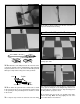
❏ 12. Cut out the holes in the cowl with a high-speed rotary tool and a small cutting bit. ❏ 2. Arrange the stopper and tubes as shown in the photo, then insert them into the tank. Tighten the screw to expand the stopper, thus sealing the tank. Be certain the fuel line weight (clunk) at the end of the fuel line inside the tank does not contact the rear of the tank. Otherwise, the line may become stuck above the fuel level and discontinue fuel flow.
FINAL ASSEMBLY Install the Remaining Servos ❏ 4. Make a mark on the bottom L.E. of each elevator 1/2" [13mm] from the inboard edge of each elevator. Position the control horn centered over the mark. Mark the hole locations on the elevator. ❏ 1. Add servo extensions to the three tail servos so that the total length of each lead will be at least 36" (914mm) from the servo to the end of the extension. Using tape or heat shrink tubing, securely attach the servo extension to the servo.
❏ 7. Thread a clevis 25 turns onto one end of each of the three 12" [305mm] pushrods. Slip a silicone retainer over the clevises. ❏ 8. Make three one-arm servo arms. Enlarge the holes in the arm with a Hobbico Servo Horn Drill (or a #48 or 5/64" (2mm) drill bit) so the pushrod will fit. ❏ 12. Screw a clevis 10 turns onto the end of the 17-1/2" [445mm] throttle pushrod. Bend the pushrod as necessary for a smooth action. ❏ 13. Glue the servo tray in place with medium CA, as shown in the photo.
Mount the Canopy ❏ 1. Use curved-tip scissors to cut out the canopy along the cut line. True the edges by sanding with medium-grit sandpaper. ❏ 16. Route the fuel lines as needed and mount the cowl, prop, muffler and spinner. ❏ 2. Place the canopy on the cockpit. Use a fine-point felt-tip pen to lightly trace the outline of the canopy onto the fuse. Option: Four #2 x 3/8" [9.5mm] screws are provided if you prefer to make the canopy removable. ❏ 3. Remove the canopy.
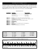
Apply the Decals Set the Control Throws 1. Use scissors or a sharp hobby knife to cut the decals from the sheet. Use a ruler to accurately measure and set the control throw of each control surface as indicated in the chart that follows. If your radio does not have dual rates, we recommend setting the throws at the low rate settings. NOTE: The throws are measured at the widest part of the elevators, rudder and ailerons. 2. Be certain the model is clean and free from oily fingerprints and dust.
Note: Do not rely upon the adhesive on the back of the lead weight to permanently hold it in place. Over time, fuel and exhaust residue may soften the adhesive and cause the weight to fall off. Use #2 sheet metal screws, RTV silicone or epoxy to permanently hold the weight in place. At this stage the model should be in ready-to-fly condition with all of the systems in place including the engine, landing gear, covering and the radio system. ❏ 1.
Balance Propellers ENGINE SAFETY PRECAUTIONS Failure to follow these safety precautions may result in severe injury to yourself and others. Keep all engine fuel in a safe place, away from high heat, sparks or flames, as fuel is very flammable. Do not smoke near the engine or fuel; and remember that engine exhaust gives off a great deal of deadly carbon monoxide. Therefore do not run the engine in a closed room or garage. Get help from an experienced pilot when learning to operate engines.
❏ 6. Use threadlocking compound to secure critical fasteners such as the set screws that hold the wheel axles to the struts, screws that hold the carburetor arm (if applicable), screw-lock pushrod connectors, etc. ❏ 7. Add a drop of oil to the axles so the wheels will turn freely. ❏ 8. Make sure all hinges are securely glued in place. ❏ 9. Reinforce holes for wood screws with thin CA where appropriate (servo mounting screws, cowl mounting screws, etc.). ❏ 10.
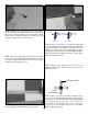
Don't get spoiled by how incredibly well the U-Can-Do 3D hangs and torque rolls! Most models take an enormous amount of work to keep the model stationary in a hanger, but the unique design of U-Can-Do 3D helps lock it solid in position and torque roll and hang with relative ease. Flight For reassurance and to keep an eye on other traffic, it is a good idea to have an assistant on the flight line with you. Tell him to remind you to throttle back once the plane gets to a comfortable altitude.
Servos PERFORMANCE SETTINGS FOR THE U-CAN-DO 3D Elevators: Ailerons: Rudder: Throttle: After testing this plane with several different engines, props, CG locations and countless different control throw settings, I found the following setup to be ideal for my particular style of flying 3D. Futaba Futaba Futaba Futaba 9250 9250 9151 9001 digital (FUTM0220) digital digital (FUTM0211) (FUTM0075) The large control throws require a servo with great centering.
OTHER ITEMS AVAILABLE FROM GREAT PLANES Futaba® S9151 Digital Rudder Servo (FUTM0211) Stock # Tx Rx Servos Tx NiCd Rx NiCd Band Modulation Stock # Tx Rx Servos Tx NiCd Rx NiCd Band Modulation FUTJ85** 9CAF R148DF (4) S3004 700mAh 600mAh 50, 72 FM Length: 1.5 in Width: 0.75 in Height: 1.4 in Weight: 1.75 oz Torque: 131.9 oz/in (4.8V) Speed: 0.19 sec @ 60° (4.8V) The S9151 delivers high-torque rudder operation for precision aerobatic aircraft.
BUILDING NOTES Kit Purchased Date: _______________________ Date Construction Finished: _________________ Where Purchased:_________________________ Finished Weight: __________________________ Date Construction Started: __________________ Date of First Flight: ________________________ FLIGHT LOG