
Assembly Instructions User guide


Drill Holes and Assemble Front Page Part Lists Great Plains Manufacturing, Inc. 5
08/21/2009 Front Page Part Lists 151-169M
Mark Holes
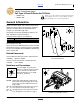
Refer to Figure 6
15. Select one new:
151-359D REAR CASTER BRACE PLATE
16. Position the brace plate at the gap . Align the
front edge of the plate with the front edge of the
weldment side plates . If it is not possible to align
the front edges, push the brace plate back against
the tube .
17. Adjust the vertical position so that all four holes
are on the center-lines .
18. If the plate cannot be positioned high enough for the
top holes to reach center-line, it may be necessary to
grind off some of the weld fillet there.
19. Using the plate as a template, mark all four holes.
Use a center-punch to make a detent at each hole
center (which may not be precisely on center-lines).
20. Repeat step 13 through step 19 for the left side of
the weldment, and both sides of the left weldment.
21. If any grinding was necessary, sand and repaint the
area prior to final assembly.
Drill Holes and Assemble
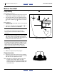
Refer to Figure 7
Start with the right side of the right caster weldment.
22. Using the pilot bit, drill a small hole at each of the 4
hole locations.
23. Using the final bit, drill the final hole at each location.
24. Select one new:
151-359D REAR CASTER BRACE PLATE
and four sets new:
802-091C HHCS 1/2-13X1 1/2 GR5
804-015C WASHER LOCK SPRING 1/2 PLT
803-020C NUT HEX 1/2-13 PLT
25. Position the plate at the outside of the weldment.
From the outside, insert all four bolts . Secure with
lock washers and nuts to torque spec:
76 ft-lbs (105 N-m)
26. Repeat step 22 through step 25 for the left side of
the weldment, and both sides of the left weldment.
Figure 6
Position a Brace
29714
3
2
12
4
1
5
7
7
U
D
B
F
12
12 1
2
3
4
5
7
12
Figure 7
Brace Installation
29712
U
D
B
F
R
L
12
13
15
14
12
13
15
14
12
13
15 14