
Assembly Instructions User guide


4 Great Plains Manufacturing, Inc. Front Page Part Lists Caster Brace Update
151-169M Front Page Part Lists 08/21/2009
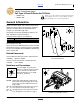
Remove Walkboard
Removing the walkboard eases access to update sites.
Refer to Figure 4
11. Loosen the four (4) nuts:
803-014C NUT HEX 3/8-16 PLT
that secure retainers:
119-032D 3-PT STEP RETAINER
12. Slide one end of the walkboard (one of):
119-296D 1006 WALKBOARD
119-303H 1006 SEED WALKBOARD WELD-
MENT
142-318D 3P1006NT FERTILIZER WALK-
BOARD
Toward drill center until clear of retainers. Slide in the
opposite direction to clear retainers at other end. Lift
walkboard off drill. Place the walkboard where no
one will injure themselves on, or damage, the Slow
Moving Vehicle reflector.
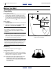
Mark Hole Locations
Mark Hole Edge Center-Lines
Start with the right side of the right caster weldment.
Refer to Figure 3
13. On the outside faces of the caster weldment plates
at each gap, mark lines parallel to the gap edge:
distance:
5
⁄
8
in (0.625in, 15.9mm)
Mark from leading edge to tube.
Check for Weldment Distortion
14. Near the weldment front, check the dimension
from center-line to center-line. The expected dis-
tance between the center-lines is:
5
1
⁄
2
in (5.50in, 14.0cm)
IMPORTANT !
If, on any face of any weldment, dimension is
greater than:
5
3
⁄
4
in (5.75in, 14.6cm)
do not install the kit. Have your dealer contact Great
Plains for further assistance.
Figure 4
Remove Walkboard
28386
54
51
52
54
51
52
52
52
6
Figure 5
Mark Center-Lines
29713
6
U
D
B
F
7
6
7
7