
Data Sheet
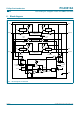
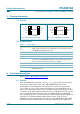
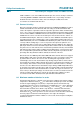
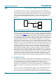
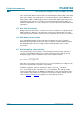
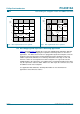
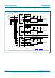
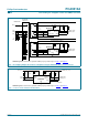
Table Of Contents
- 1. General description
- 2. Features
- 3. Applications
- 4. Feature selection
- 5. Ordering information
- 6. Block diagram
- 7. Pinning information
- 8. Functional description
- 9. Application design-in information
- 10. Limiting values
- 11. Characteristics
- 12. Test information
- 13. Package outline
- 14. Soldering
- 15. Abbreviations
- 16. Revision history
- 17. Data sheet status
- 18. Definitions
- 19. Disclaimers
- 20. Trademarks
- 21. Contact information
- 22. Contents
PCA9512A_1 © Koninklijke Philips Electronics N.V. 2005. All rights reserved.
Product data sheet Rev. 01 — 7 October 2005 8 of 22
Philips Semiconductors
PCA9512A
Level shifting hot swappable I
2
C-bus and SMBus bus buffer
8.8 Hot swapping and capacitance buffering application
Figure 7 through Figure 9 illustrate the usage of the PCA9512A in applications that take
advantage of both its hot swapping and capacitance buffering features. In all of these
applications, note that if the I/O cards were plugged directly into the backplane, all of the
backplane and card capacitances would add directly together, making rise time and
fall time requirements difficult to meet. Placing a bus buffer on the edge of each card,
however, isolates the card capacitance from the backplane. For a given I/O card, the
PCA9512A drives the capacitance of everything on the card and the backplane must drive
only the capacitance of the bus buffer, which is less than 10 pF, the connector, trace, and
all additional cards on the backplane.
See
Application Note AN10160, ‘Hot Swap Bus Buffer’
for more information on
applications and technical assistance.
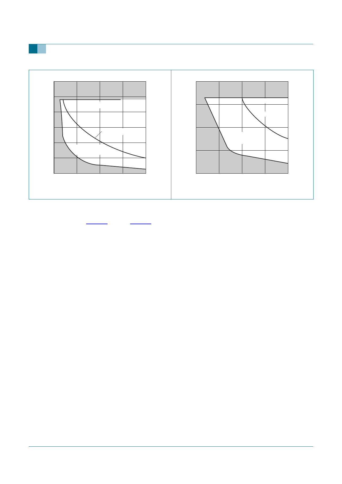
Fig 5. Bus requirements for 3.3 V systems Fig 6. Bus requirements for 5 V systems
C
b
(pF)
0 400300100 200
002aab582
10
20
30
R
PU
(kΩ)
0
recommended
pull-up
rise time > 300 ns
R
max
= 24 kΩ
C
b
(pF)
0 400300100 200
002aab583
10
5
15
20
R
PU
(kΩ)
0
recommended
pull-up
rise time > 300 ns
R
max
= 16 kΩ