
Data Sheet

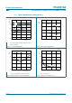
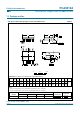

Table Of Contents
- 1. General description
- 2. Features
- 3. Applications
- 4. Feature selection
- 5. Ordering information
- 6. Block diagram
- 7. Pinning information
- 8. Functional description
- 9. Application design-in information
- 10. Limiting values
- 11. Characteristics
- 12. Test information
- 13. Package outline
- 14. Soldering
- 15. Abbreviations
- 16. Revision history
- 17. Data sheet status
- 18. Definitions
- 19. Disclaimers
- 20. Trademarks
- 21. Contact information
- 22. Contents

PCA9512A_1 © Koninklijke Philips Electronics N.V. 2005. All rights reserved.
Product data sheet Rev. 01 — 7 October 2005 20 of 22
Philips Semiconductors
PCA9512A
Level shifting hot swappable I
2
C-bus and SMBus bus buffer
[4] These packages are not suitable for wave soldering. On versions with the heatsink on the bottom side, the
solder cannot penetrate between the printed-circuit board and the heatsink. On versions with the heatsink
on the top side, the solder might be deposited on the heatsink surface.
[5] If wave soldering is considered, then the package must be placed at a 45° angle to the solder wave
direction. The package footprint must incorporate solder thieves downstream and at the side corners.
[6] Wave soldering is suitable for LQFP, QFP and TQFP packages with a pitch (e) larger than 0.8 mm; it is
definitely not suitable for packages with a pitch (e) equal to or smaller than 0.65 mm.
[7] Wave soldering is suitable for SSOP, TSSOP, VSO and VSSOP packages with a pitch (e) equal to or larger
than 0.65 mm; it is definitely not suitable for packages with a pitch (e) equal to or smaller than 0.5 mm.
[8] Image sensor packages in principle should not be soldered. They are mounted in sockets or delivered
pre-mounted on flex foil. However, the image sensor package can be mounted by the client on a flex foil by
using a hot bar soldering process. The appropriate soldering profile can be provided on request.
[9] Hot bar soldering or manual soldering is suitable for PMFP packages.
15. Abbreviations
16. Revision history
Table 7: Abbreviations
Acronym Description
AdvancedTCA Advanced Telecommunications Computing Architecture
CDM Charged Device Model
cPCI compact Peripheral Component Interface
ESD Electrostatic Discharge
HBM Human Body Model
I
2
C-bus Inter IC bus
MM Machine Model
PCI Peripheral Component Interface
PICMG PCI Industrial Computer Manufacturers Group
SMBus System Management Bus
VME VERSAModule Eurocard
Table 8: Revision history
Document ID Release date Data sheet status Change notice Doc. number Supersedes
PCA9512A_1 20051007 Product data sheet - - -