
Data Sheet

TCS3404, TCS3414
DIGITAL COLOR SENSORS
TAOS137A − APRIL 2011
4
r
r
Copyright E 2011, TAOS Inc.
The LUMENOLOGY r Company
www.taosinc.com
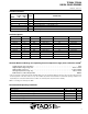
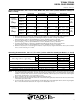
Electrical Characteristics, T
A
= 25C (unless otherwise noted)
PARAMETER TEST CONDITIONS MIN TYP MAX UNIT
Power on (ADC inactive)
7.7 10 mA
I
DD
Supply current @ V
DD
= 3.6 V
Power on (ADC active)
8.7 11 mA
I
DD
Supply
current
@
V
DD
3.6
V
Power down
700 1000 μA
V
OL
INT, SDA output low voltage 3 mA sink current 0 0.4 V
I
LEAK
Input leakage current (SDA, SCL, SYNC) V
IH
= V
DD,
V
IL
= GND −5 5 μA
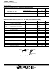
AC Electrical Characteristics, V
DD
= 3.3 V, T
A
= 25C (unless otherwise noted)
PARAMETER
†
TEST CONDITIONS MIN TYP MAX UNIT
f
Clock frequency 400 kHz (I
2
C) 0 400 kHz
f
(SCL)
Clock frequency 100 kHz (SMBus) 10 100 kHz
t
(BUF)
Bus free time between start and stop condition 1.3 μs
t
(HDSTA)
Hold time after (repeated) start condition. After
this period, the first clock is generated.
0.6 μs
t
(SUSTA)
Repeated start condition setup time 0.6 μs
t
(SUSTO)
Stop condition setup time 0.6 μs
t
(HDDAT)
Data hold time 0 0.9 μs
t
(SUDAT)
Data setup time 100 ns
t
(LOW)
SCL clock low period 1.3 μs
t
(HIGH)
SCL clock high period 0.6 μs
t
(TIMEOUT)
Detect clock/data low timeout (SMBus only) 25 35 ms
t
F
Clock/data fall time 300 ns
t
R
Clock/data rise time 300 ns
C
i
Input pin capacitance 10 pF
t
LOW
(SYNC)
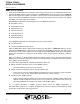
SYNC low period (see Figure 1) 50 μs
t
HIGH
(SYNC)
SYNC high period (see Figure 1) 50 μs
t
F
(SYNC)
SYNC fall time (see Figure 1) 50 ns
t
R
(SYNC)
SYNC rise time (see Figure 1) 50 ns
†
Specified by design and characterization; not production tested.
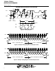
t
HIGH
(SYNC)
t
F
(SYNC)
t
R
(SYNC)
t
LOW
(SYNC)
Figure 1. Timing Diagram for Sync