
Data Sheet

TCS3404, TCS3414
DIGITAL COLOR SENSORS
TAOS137A − APRIL 2011
32
r
r
Copyright E 2011, TAOS Inc.
The LUMENOLOGY r Company
www.taosinc.com
APPLICATION INFORMATION: HARDWARE
Power Supply Decoupling and Application Hardware Circuit
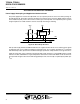
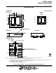
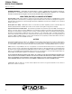
The power supply lines must be decoupled with a 0.1 μF capacitor placed as close to the device package as
possible (Figure 28). The bypass capacitor should have low effective series resistance (ESR) and low effective
series inductance (ESI), such as the common ceramic types, which provide a low impedance path to ground
at high frequencies to handle transient currents caused by internal logic switching.
TCS3404/14
V
BUS
V
DD
0.1 F
R
P
R
P
SCL
SDA
R
PI
INT
Figure 28. Bus Pull-Up Resistors
Pull-up resistors (Rp) maintain the SDA and SCL lines at a high level when the bus is free and ensure the signals
are pulled up from a low to a high level within the required rise time. For a complete description of I
2
C maximum
and minimum Rp values, please review the NXP I
2
C design specification at http://www.i2c−bus.org/references/.
A pull-up resistor (R
PI
) is also required for the interrupt (INT), which functions as a wired-AND signal in a similar
fashion to the SCL and SDA lines. A typical impedance value between 10 kΩ and 100 kΩ can be used. Please
note that while the figure above shows INT being pulled up to V
DD
, the interrupt can optionally be pulled up to
V
BUS
.