
Data Sheet

TCS3404, TCS3414
DIGITAL COLOR SENSORS
TAOS137A − APRIL 2011
3
The LUMENOLOGY r Company
r
r
Copyright E 2011, TAOS Inc.
www.taosinc.com
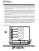
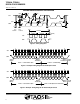
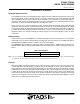
Terminal Functions
TERMINAL
NAME
CS PKG
NO.
FN PKG
NO.
TYPE DESCRIPTION
GND A3 6 Power supply ground. All voltages are referenced to GND.
INT B3 4 O Level interrupt — open drain.
SCL A1 1 I Serial clock input terminal — clock signal for I
2
C serial data.
SDA B1 3 I/O Serial data I/O terminal — serial data I/O for I
2
C.
SYNC A2 2 I Synchronous input.
V
DD
B2 5 Supply voltage.
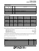
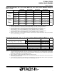
Available Options
DEVICE INTERFACE I
2
C ADDRESS PACKAGE − LEADS PACKAGE DESIGNATOR ORDERING NUMBER
TCS3404 SMBus − Chipscale−6 CS TCS3404CS
TCS3404 SMBus − Dual Flat No-Lead−6 FN TCS3404FN
TCS3413 I
2
C 0x29 Chipscale−6 CS TCS3413CS
TCS3413 I
2
C 0x29 Dual Flat No-Lead−6 FN TCS3413FN
TCS3414
†
I
2
C 0x39 Chipscale−6 CS TCS3414CS
TCS3414
†
I
2
C 0x39 Dual Flat No-Lead−6 FN TCS3414FN
TCS3415 I
2
C 0x49 Chipscale−6 CS TCS3415CS
TCS3415 I
2
C 0x49 Dual Flat No-Lead−6 FN TCS3415FN
TCS3416 I
2
C 0x59 Chipscale−6 CS TCS3416CS
TCS3416 I
2
C 0x59 Dual Flat No-Lead−6 FN TCS3416FN
†
Recommended device for single-device systems..
Absolute Maximum Ratings over operating free-air temperature range (unless otherwise noted)
†
Supply voltage, V
DD
(see Note 1) 3.8 V. . . . . . . . . . . . . . . . . . . . . . . . . . . . . . . . . . . . . . . . . . . . . . . . . . . . . . . . . . .
Digital output voltage range, V
O
−0.5 V to 3.8 V. . . . . . . . . . . . . . . . . . . . . . . . . . . . . . . . . . . . . . . . . . . . . . . . . . . .
Digital output current, I
O
−1 mA to 20 mA. . . . . . . . . . . . . . . . . . . . . . . . . . . . . . . . . . . . . . . . . . . . . . . . . . . . . . . . . .
Storage temperature range, T
stg
−40°C to 85°C. . . . . . . . . . . . . . . . . . . . . . . . . . . . . . . . . . . . . . . . . . . . . . . . . . . .
ESD tolerance, human body model 2000 V. . . . . . . . . . . . . . . . . . . . . . . . . . . . . . . . . . . . . . . . . . . . . . . . . . . . . . . .
†
Stresses beyond those listed under “absolute maximum ratings” may cause permanent damage to the device. These are stress ratings only, and
functional operation of the device at these or any other conditions beyond those indicated under “recommended operating conditions” is not
implied. Exposure to absolute-maximum-rated conditions for extended periods may affect device reliability.
NOTE 1: All voltages are with respect to GND.
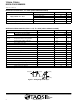
Recommended Operating Conditions
MIN NOM MAX UNIT
Supply voltage, V
DD
2.7 3 3.6 V
Operating free-air temperature, T
A
(CS PAckage) −40 85 °C
Operating free-air temperature, T
A
(FN PAckage) −30 70 °C
SCL, SDA input low voltage, V
IL
−0.5 0.8 V
SCL, SDA input high voltage, V
IH
2.1 3.6 V