
Data Sheet

TCS3404, TCS3414
DIGITAL COLOR SENSORS
TAOS137A − APRIL 2011
20
r
r
Copyright E 2011, TAOS Inc.
The LUMENOLOGY r Company
www.taosinc.com
Interrupt Threshold Register (08h − 0Bh)
The interrupt threshold registers store the values to be used as the high and low trigger points for the comparison
function for interrupt generation. The high and low bytes from each set of registers are combined to form a 16-bit
threshold value. If the value generated by the Interrupt Source Register (03h) converges below or equal to the
low threshold specified, an interrupt is asserted on the interrupt pin. If the value generated by Interrupt Source
Register (03h) converges above the high threshold specified, an interrupt is asserted on the interrupt pin.
Registers LOW_THRESH_LOW_BYTE and LOW_THRESH_HIGH_BYTE provide the low byte and high byte,
respectively, of the lower interrupt threshold. Registers HIGH_THRESH_LOW_BYTE and
HIGH_THRESH_HIGH_BYTE provide the low and high bytes, respectively, of the upper interrupt threshold.
The interrupt threshold registers default to 00h on power up.
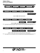
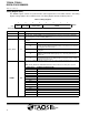
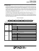
Table 10. Interrupt Threshold Register
REGISTER ADDRESS BITS DESCRIPTION
LOW_THRESH_LOW_BYTE 08h 7:0 ADC interrupt source lower byte of the low threshold.
LOW_THRESH_HIGH_BYTE 09h 7:0 ADC interrupt source upper byte of the low threshold.
HIGH_THRESH_LOW_BYTE 0Ah 7:0 ADC interrupt source lower byte of the high threshold.
HIGH_THRESH_HIGH_BYTE 0Bh 7:0 ADC interrupt source upper byte of the high threshold.
NOTES: 1. The Interrupt Source Register (03h) selects which ADC channel to generate an interrupt and should correspond to the threshold
setting. Both registers should be configured appropriately when setting up an interrupt service routine.
2. Since two 8-bit values are combined for a single 16-bit value for each of the high and low interrupt thresholds, the SMBus Send Byte
protocol should not be used to write to these registers. Any values transferred by the Send Byte protocol with the MSB set would
be interpreted as the COMMAND field and stored as an address for subsequent read/write operations and not as the interrupt
threshold information as desired. The Write Word protocol should be used to write byte-paired registers. For example, the
LOW_THRESH_LOW_BYTE and LOW_THRESH_HIGH_BYTE registers (as well as the HIGH_THRESH_LOW_BYTE and
HIGH_THRESH_HIGH_BYTE registers) can be written together to set the 16-bit ADC value in a single transaction.
ADC Channel Data Registers (10h − 17h)
The ADC channel data are expressed as 16-bit values spread across four registers. The channel low and high
provide the lower and upper bytes respectively for each ADC channel data registers. Each DATALOW and
DATAHIGH register is identified below as 1, 2, 3, or 4. All channel data registers are read-only and default to
00h on power up.
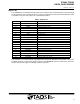
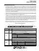
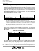
Table 11. ADC Channel Data Registers
REGISTER ADDRESS BITS DESCRIPTION
GREEN_LOW 10h 7:0 ADC channel 1 lower byte
GREEN_HIGH 11h 7:0 ADC channel 1 upper byte
RED_LOW 12h 7:0 ADC channel 2 lower byte
RED_HIGH 13h 7:0 ADC channel 2 upper byte
BLUE_LOW 14h 7:0 ADC channel 3 lower byte
BLUE_HIGH 15h 7:0 ADC channel 3 upper byte
CLEAR_LOW 16h 7:0 ADC channel 4 lower byte
CLEAR_HIGH 17h 7:0 ADC channel 4 upper byte
The upper byte data registers can only be read following a read to the corresponding lower byte register. When
the lower byte register is read the upper eight bits are strobed into a shadow register, which is read by a
subsequent read to the upper byte. The upper register will therefore read the correct value even if additional
ADC integration cycles complete between the reading of the lower and upper registers.
NOTE: The SMBus Read Word protocol can be used to read byte-paired registers. For example, the DATA1LOW and DATA1HIGH registers (as
well as the other three individual register pairs) may be read together to obtain the 16-bit ADC value in a single transaction.