
Data Sheet

TCS3404, TCS3414
DIGITAL COLOR SENSORS
TAOS137A − APRIL 2011
17
The LUMENOLOGY r Company
r
r
Copyright E 2011, TAOS Inc.
www.taosinc.com
Interrupt Control Register (02h)
The INTERRUPT register controls the extensive interrupt capabilities of the device. The open-drain interrupt
pin is active low and requires a pullup resistor to V
DD
in order to pull high in the inactive state. Using the Interrupt
Source Register (03h), the interrupt can be configured to trigger on any one of the four ADC channels. The
TCS3404/14 permits both SMB-Alert style interrupts as well as traditional level style interrupts. The Interrupt
Register provides control over when a meaningful interrupt will occur. The concept of a meaningful change can
be defined by the user both in terms of light intensity and time, or persistence of that change in intensity. The
value must cross the threshold (as configured in the Threshold Registers 08h through 0Bh) and persist for some
period of time as outlined in the table below.
When a level Interrupt is selected, an interrupt is generated whenever the last conversion results in a value
outside of the programmed threshold window. The interrupt is active-low and remains asserted until cleared by
writing an 11 in the TRANSACTION field in the COMMAND register.
In SMB-Alert mode, the interrupt is similar to the traditional level style and the interrupt line is asserted low. To
clear the interrupt, the host responds to the SMB-Alert by performing a modified Receive Byte operation, in
which the Alert Response Address (ARA) is placed in the slave address field, and the TCS3404/14 that
generated the interrupt responds by returning its own address in the seven most significant bits of the receive
data byte. If more than one device connected on the bus has pulled the SMBAlert line low, the highest priority
(lowest address) device will win control of the bus during the slave address transfer. If the device loses this
arbitration, the interrupt will not be cleared. The Alert Response Address is 0Ch.
When INTR = 11, the interrupt is generated immediately following the SMBus write operation. Operation then
behaves in an SMB-Alert mode, and the software set interrupt may be cleared by an SMB-Alert cycle.
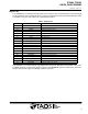
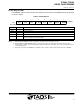
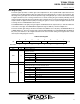
Table 6. Interrupt Control Register
67542310
0000 0000Reset Value:
INTERRUPT
INTR_STOPResv INTR Resv
02h
PERSIST
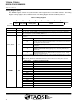
FIELD BITS DESCRIPTION
Resv 7 Reserved. Write as 0.
INTR_STOP 6
Stop ADC integration on interrupt. When high, ADC integration will stop once an interrupt is asserted.
To resume operation (1) de-assert ADC_EN using CONTROL register, (2) clear interrupt using
COMMAND register, and (3) re-assert ADC_EN using CONTROL register. Note: Use this bit to isolate
a particular condition when the sensor is continuously integrating.
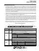
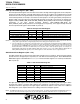
INTR Control Select. This field determines mode of interrupt logic according to the table below:
FIELD VALUE INTERRUPT CONTROL
00 Interrupt output disabled.
INTR
5:4
01 Level Interrupt.
INTR
5
:
4
10 SMB-Alert compliant.
11 Sets an interrupt and functions as mode 10.
NOTE: Value 11 may be used to test interrupt connectivity in a system or to assist in debugging interrupt
service routine software. See Application Software section for further information.
Resv 3 Reserved. Write as 0.
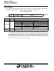
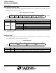
Interrupt persistence. Controls rate of interrupts to the host processor:
FIELD VALUE TIMER DESCRIPTION
PERSIST
2:0
000 Every Every ADC cycle generates interrupt
PERSIST 2:0
001 Single Any value outside of threshold range.
010 0.1 sec Consecutively out of range for 0.1 second
011 1 sec Consecutively out of range for 1 second