
Data Sheet

TCS3404, TCS3414
DIGITAL COLOR SENSORS
TAOS137A − APRIL 2011
14
r
r
Copyright E 2011, TAOS Inc.
The LUMENOLOGY r Company
www.taosinc.com
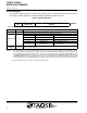
Command Register
The command register specifies the address of the target register for subsequent read and write operations.
This register contains eight bits as described in Table 3 and defaults to 00h at power on.
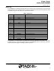
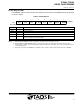
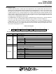
Table 3. Command Register
6754
ADDRESS
2310
0000 0000Reset Value:
COMMAND
CMD TRANSACTION
FIELD BITS DESCRIPTION
CMD 7 Select command register. Must write as 1.
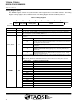
Transaction. Selects type of transaction to follow in subsequent data transfer.
FIELD VALUE TRANSACTION DESCRIPTION
00 Byte protocol SMB read/write byte protocol
TRANSACTION 6:5
01 Word protocol SMB read/write word protocol
10 Block protocol SMB read/write block protocol
11 Interrupt clear
Clear any pending interrupt and is a write-
once-to-clear field
ADDRESS 4:0
Register Address. This field selects the specific control or status register for following write and read com-
mands according to Table 2.
NOTES: 1. An I
2
C block transaction will continue until the Master sends a stop condition. See Figure 18 and Figure 19. Unlike the I
2
C protocol,
the TCS3404/14 SMBus read/write protocol requires a Byte Count. All eight ADC Channel Data Registers (10h through 17h) can
be read simultaneously in a single SMBus transaction. This is the only 64-bit data block supported by the TCS3404 SMBus protocol.
The TRANSACTION field must be set to 10, and a read condition should be initiated with a COMMAND CODE of CFh. By using
a COMMAND CODE of CFh during an SMBus Block Read Protocol, the TCS3404 device will automatically insert the appropriate
Byte Count (Byte Count = 8) as illustrated in Figure 18. A write condition should not be used in conjunction with the 0Fh register.
2. Only the Send Byte Protocol should be used when clearing interrupts.