
Data Sheet

TCS3404, TCS3414
DIGITAL COLOR SENSORS
TAOS137A − APRIL 2011
13
The LUMENOLOGY r Company
r
r
Copyright E 2011, TAOS Inc.
www.taosinc.com
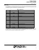
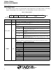
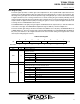
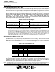
Register Set
The TCS3404/14 is controlled and monitored by 18 user registers and a command register accessed through
the serial interface. These registers provide for a variety of control functions and can be read to determine results
of the ADC conversions. The register set is summarized in Table 2.
Table 2. Register Set
ADDRESS REGISTER NAME REGISTER FUNCTION
−− COMMAND Specifies register address
00h CONTROL Control of basic functions
01h TIMING Integration time/gain control
02h INTERRUPT Interrupt control
03h INT SOURCE Interrupt source
04h ID Part number/ Rev ID
07h GAIN ADC gain control
08h LOW_THRESH_LOW_BYTE Low byte of low interrupt threshold
09h LOW_THRESH_HIGH_BYTE High byte of low interrupt threshold
0Ah HIGH_THRESH_LOW_BYTE Low byte of high interrupt threshold
0Bh HIGH_THRESH_HIGH_BYTE High byte of high interrupt threshold
0Fh −− SMBus block read (10h through 17h)
10h DATA1LOW Low byte of ADC green channel
11h DATA1HIGH High byte of ADC green channel
12h DATA2LOW Low byte of ADC red channel
13h DATA2HIGH High byte of ADC red channel
14h DATA3LOW Low byte of ADC blue channel
15h DATA3HIGH High byte of ADC blue channel
16h DATA4LOW Low byte of ADC clear channel
17h DATA4HIGH High byte of ADC clear channel
The mechanics of accessing a specific register depends on the specific SMB protocol used. Refer to the section
on SMBus protocols on the previous pages. In general, the COMMAND register is written first to specify the
specific control/status register for following read/write operations.