
Instructions for use

97 / 116
S1002.PRO_mz12PRO_Teil2_V1sh
If, on the other hand, a sensor uses a firmware from an older
firmware package than the one used in the receiver, it may be
necessary to select "etc." instead of the direct selection of the
sensor.
4. Use the right selection button to change to the displays of the
selected device and to change these settings or to change the set-
tings as described in the instructions supplied with the device.
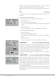
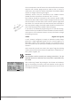
SENSOR
If a sensor or several sensors have been connected to the receiver
before the receiver is switched on, the transmitter mz-12 Pro HoTT
detects this automatically in the course of setting up the telemetry
connection.
After selecting the desired menu line, pressing the SET key opens the
selected submenu.
Active (
) or inactive ( ) sensors are automatically labelled in this
submenu provided that a telemetry link exists. Manual sensor selec-
tion is then unnecessary and impossible.
The corresponding graphic displays are activated automatically and
the corresponding setting pages can be selected accordingly in the
"SETTING & DATA VIEW" submenu described above.
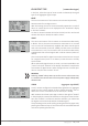
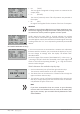
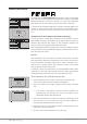
Display of RF status
After selecting the desired menu line, pressing the SET key opens the
selected submenu. This visualises the quality of the connection
between transmitter and receiver.
• Upper row
Level of channels 1 … 75 coming from the receiver of the 2.4 GHz
band in dBm at the transmitter.
• Lower row
Level of channels 1 … 75 coming from the transmitter of the 2.4
GHz band in dBm at the receiver.
Note
• The height of the bar is a measure of the reception level expressed
as logarithmic values with the unit dBm (1 mW = 0 dBm).
• 0 dBm corresponds to the two baselines in the above graph. Con-
sequently, the level is poorer the higher the bar and vice versa,
see also "S-dBm (reception level)" in the section "RX DATAVIEW".
• The points over the bar mark the worst reception levels since the
transmitter was switched on or the display was reset by pressing
the transmitter's left and right selection buttons (CLEAR) at the
same time.
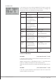
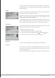
TELEMETRY
SETTING & DATA VIEW
SENSOR
RF STATUS DISPLAY
SELECT ANNOUNCE
RX DATA ON
ALARM SETTING
SENSOR
RECEIVER
GENERAL MODULE
VARIO MODULE
ELECTR. AIR MODULE
GPS
ESC
TELEMETRY
SETTING & DATA VIEW
SENSOR
RF STATUS DISPLAY
SELECT ANNOUNCE
RX DATA ON
ALARM SETTING
E100%
T –40
P 10
R –51
4.8RS
S 90%
4.8RM 0123456789ABCDE