
Instructions for use

95 / 116
S1002.PRO_mz12PRO_Teil2_V1sh
The most important control function should therefore be associated
with the main receiver programmed as SUMI so that, in case of a
malfunction, the model can still be controlled if the SUMO satellite
receiver no longer receives a good signal.
Telemetry sensors must be connected to the satellite receiver
(SUMO) and this is therefore to be bound "last" as a rule.
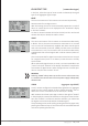
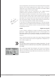
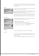
Each receiver should be connected to the common power supply
with its own cable. With receivers subject to high current load, it may
even be useful to connect them to the common power supply with
two cables. If in contrast each of the two receivers are connected to
their own power supply, the middle cable should be removed from
one of the two plugs of the satellite cable (see figure).
If you wish to do additional programming such as fail safe settings,
disconnect the 3-pin satellite connection between the two receivers,
and only turn on the relevant receiver. You may also have to change
the binding sequence.
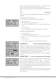
SUMD (digital sum signal))
A HoTT receiver configured as SUMD as described earlier always
generates a digital aggregate signal from the control signals of a
selectable number of its controls channels, and forwards this to
servo connection 8 in the GR-16 (No. 33508) and GR-24 (No. 33512)
receivers.
At the time this manual was revised, this type of signal was being
used by several of the latest electronic applications of flybarless sys-
tems, power supplies, etc.
Attention
You therefore need to consult your setting instructions for the
attached device since otherwise you may make it impossible to fly
the model.
After confirming "SUMD" by pushing the ENT button at the bottom
right in the display, the active value field switches to the right for
selecting one of the three possible receiver reactions in case of a loss
of reception (fail safe):
rot
1
2
3
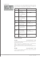
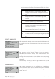
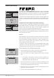
RX SERVO TESTV6.37
ALL–MIN : 1000µsec
ALL–MAX : 2000µsec
ALARM VOLT : 3.8V
ALARM TEMP–:–10°C
ALARM TEMP+: 55°C
TEST : START
CH OUT TYPE:SUMDHD12