
Instructions for use

59 / 116
S1002.PRO_mz12PRO_Teil2_V1sh
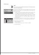
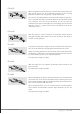
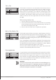
Tail => Thr
The throttle is increased on one side where the tail rotor thrust is
increased. The setting range is therefore only 0 to +100%. The direc-
tion is dependent on the rotation of the main rotor (left or right),
which must be set correctly in the submenu "Model type" of the
"Model type and phase adjustment" menu. In the case of left-rotat-
ing systems, the throttle is taken when the tail rotor control stick
moves to the left, and to the right when the main rotor rotates to
the right.
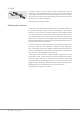
Mixer setting step-by-step
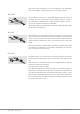
1. Push the ENT key to activate the value field.
2. Use the selection buttons to set the desired value or, by pressing
the left and right selection buttons simultaneously, reset the cur-
rent value to the default value "0%".
3. Press the ENT or the ESC key to complete the operation.
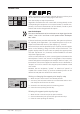
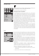
Roll => Thr / Nick => Thr
The throttle needs to follow an increase in pitch; likewise, the throt-
tle should track with large cyclical control movements, that is, tilting
a swashplate in a desired direction. In the mz-12 Pro HoTT transmit-
ter programs, throttle tracking with roll, pitch and tail control can be
attempted separately.
This is advantageous especially with aerobatics (for example when
performing rolls) since cyclical control deflections are used with mid-
dle collective pitch values where the carburettor is about halfway
open that require significantly higher motor output.
The mixer value can be set between 0 and +100 %. The correct mixer
direction is automatically taken into account.
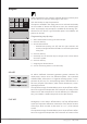
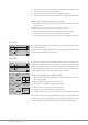
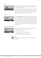
Gyro suppression
If a gyro system is used in which the gyro can be adjusted via an addi-
tional channel from the transmitter, this option can be used to influ-
ence the effect of the gyro sensor ("gyro") as a function of the tail
rotor actuation. The gyro suppression reduces the gyro's effect in a
linear manner in proportion to the deflection of the tail rotor control
stick corresponding to the set value.
Attention
This option may normally not be used for current standard gyro sys-
tems. In this connection it is absolutely necessary to observe the
adjustment instructions enclosed with the respective gyro, as oth-
erwise the helicopter in question is non-flyable.
C1
C1
Pitch
Thr
Tail
normal
0%
0%
Tail
Thr
Thr
Roll
C1
C1
Thr
Tail
normal
0%
0%
Tail
Thr
Thr
Roll
Thr
Nick 0%
C1
Tail
normal
0%
0%
Tail
Thr
Thr
Roll
Thr
Nick 0%
Gyro suppression
0%