EN Manual mz-12 PRO 12 channel HoTT 2,4 GHz transmitter Copyright © Graupner/SJ GmbH No. S1002.
Index Introduction............................................................................... 9 Service center............................................................................. 9 Intended use ............................................................................ 10 Target group...................................................................................10 Package content....................................................................... 10 Symbol description...................
Delete model.................................................................................23 Copy Mod=>Mod...........................................................................24 Model types/Phase.................................................................. 25 Model type (Air, land and water models)......................................25 Motor on CH1.............................................................................25 Throttle Cut......................................................
Throttle curve........................................................................... 52 Wing Mix.................................................................................. 53 Aile diff...........................................................................................53 FLAP diff.........................................................................................53 AI => RU.........................................................................................54 AI => FL.............
Preparing for training mode..........................................................70 Trainer mode with DSC cable........................................................72 Wireless HoTT system....................................................................72 Announce................................................................................. 73 Info display............................................................................... 74 RFID.......................................................
VARIO...........................................................................................107 Microcopter display.................................................................107 Vario..........................................................................................108 Text displays..............................................................................108 GPS...............................................................................................108 Microcopter display.........
/ 116 S1002.
Introduction Thank you very much for purchasing a Graupner transmitter. The transmitter manual is composed by two parts: Part 1, the printed short-manual, is included in the package. Part 2, the programming manual, can be found in its last version on www.graupner.de by the related page of the transmitter. Read the manual carefully to use the transmitter optimally and first of all to safely control your models.
Intended use This transmitter system must only be used for the purpose specified by the manufacturer for operation of remote control models without passengers. Any other type of use is impermissible and may cause significant property damage and/or personal injury. No warranty or liability is therefore offered for any improper use not covered by these provisions.
Symbol description Always observe the information indicated by these warning signs. Particularly those which are additionally marked with the words CAUTION or WARNING. ! The signal word WARNING indicates the potential for serious injury, the signal word CAUTION indicates possibility of lighter injuries. The signal word Note indicates potential malfunctions. Attention indicates potential damages to objects.
Foreword The manual of this transmitter is made of two parts: The one named Part 1 quick guide is included in the package of the transmitter and this Part 2 in form of programming manual is always updated and is available as download in the web page of the related item on www.graupner.de. Read both manuals carefully to use the transmitter optimally und first of all to safely control your models.
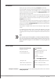
Short-Cuts The following key combinations can be used to call up certain menus and options: CLEAR Simultaneous touch of the left and the right keys of the left four way keypad will restore the active entry field's changed parameter value back to its default value.
Definition of terms Control function A control function is understood as the signal for a specific control function. The signal of a control function can be transmitted directly into one control channel or through a mixer to several control channels. The control function includes the influence of the mechanical control path on the corresponding servo. This can be spread or concentrated and modified from linear to highly exponential.
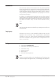
Meaning of the warnings Batter y must be charged !! Transmitter voltage too low BIND? OK Bind? No receiver is bound to the actually active model memory. By tapping the ENT button you can accede the related option. CAN‘T RECEIVE ANY DATA OK RF ON/OFF? ON OFF SWITCH RF OFF OK Fail-Safe setting! Throttle too high! No pupil Signal No bound receiver in range.
Receiver assignation The servos must be connected to the receiver in the indicated sequence. Not assigned outputs remain free. Details about the receiver power supply can be found in the related receiver system manual.
Delta/flying-wing models with and without motor with up to 2 aileron/elevator servos and 2 flap/elevator servos free or special function or flap 2 / elev right free or special function or flap 2 / elev left free or special function free or special function receiver power supply free or flap / elev right fre or flap / elev left free or special function free or rudder aile/elev right aile/elev left Airbrake or motor servo or ESC for electric models receiver power supply free or special function Due to the d
Helicopter models with 1 to 3 swashplate servos free or speed controller Throttle servo or governor receiver power supply free or special function tail servo (gyro system) servo 1 Nick servo 1 Roll receiver power supply servo Pitch or Roll 2 or Nick 2 gyro action with 4 swashplate servos free or speed controller throttle servo or governor receiver power supply servo Nick 2 tail servo (gyro system) servo Nick 1 servo Roll 1 receiver power supply servo Roll 2 gyro action Note Completely independent from th
Land and water models free or special function free or special function free or special function free or special function free or special function free or special function steering (left/right) receiver power supply Motor servo or ESC (forward/backward) free or special function Copter free or special function free or special function receiver power supply free or special function Yaw Nick Roll receiver power supply Motor/Pitch (climb/sink) free or special function Note Completely independent from the "c
Control, switch and control switch assignment Controls assignment In the"Ctl setting" menu, it is possible to assign to the transmitter-side inputs E5 to E12 or E5, Throttle, Gyr, E8 to E11 and Lim proportional rotary knobs as well as any of the 2 or 3 position switches mounted on the transmitter to control any servo. Programming step-by-step Move the desired switch or control 1. Move to the related column with the selection keys. 2. Move the desired switch or control to the OFF position. 3.
Digital trim / Throttle switch-off trim current trim position last idle position 0:00 0:00 Stop Flight 5.2V 3:33h K78 2.4 M RX0.0V Idle direction C1 trim lever GRAUBELE #01 Trim in Motor OFF position current Trim position last idle position GRAUBELE #01 Throttle limit control 0:00 0:00 Stop Flight 5.2V 3:33h K78 2.4DG RX0.0V N R Trim in Motor OFF position S1002.PRO_mz12PRO_Teil2_V1sh The two control sticks come with digital trimming.
Menu description The menus are described in the same sequence as they appear in the display. Model memory Model M.Type Servo Ctl memory Phase setting setting D/R Expo C1 Tx setting curve Wing mix Push the ENT key to recall the selection menu from the base display. Push again the ENT button to recall the list of the sub-menus of the "Model memory" menu. Push the ESC key to stop the procedure.
Note If the actually active model memory is deleted, soon after the deletion process it must be defined a favorite model type. This selection can also be restored by switching the transmitter off. After all, the unwanted occupied model memory is to be erased from another memory. Model name => Model select Model name Delete model Copy Mod–>Mod => => => You can insert a maximum of nine characters for a model name of the active model memory.
Notes • This deletion cannot be restored. All of the data in the selected model memory are completely deleted. • If the currently active model memory is deleted, a model type must be defined immediately afterwards. If an inactive model memory is deleted, soon after the model selection appears "àààfreeààà".
Model types/Phase Model M.Type Servo Ctl memory Phase setting setting D/R Expo Tx setting C1 curve Model type Phase setting Phase trim Wing mix => => => => => Push the ENT key to recall the selection menu from the base display. Push the ESC key to stop the procedure. Select the desired menu with the selection buttons, then press the ENT button again to recall the list of the submenu Model Type / Phase. In this menu the "type" of the model to be programmed is defined.
The brake system is retracted in the back position of the throttle / brake control stick (CH1), and the mixers "CH1 => N.N. *" in the "Wing mix" menu are activated. The warning "Throttle too high!" is deactivated and the "Throttle cut" option is not shown in the display. Throttle Cut Note This option is not shown if "none" or "none/inv" is set in the line "Motor on CH1". back Motor at C1 M.Stop –100% +150% ––– Tail normal Aile.
Programming step-by-step back Motor at C1 M.Stop –100% +150% ––– Tail normal Aile./Flap 1AI back Motor at C1 M.Stop –100% +150% ––– Tail normal Aile./Flap 1AI 1. In the left column of the "M-Stop" line, press the ENT key. 2. Use the selection buttons to set a value at which the motor is reliably "off". ശശ In the case of an i.e. engine, care must be taken that the throttle servo does not run mechanically over. 3. Push the ENT key. 4. Use the right selection key to switch to the middle setting field. 5.
"Delta/flying wing" This option is only suitable for Delta and Flying wing models. The aileron and elevator control are carried out through one or two servos each half-wing. The elevator and aileron trim acts according to your settings of "2AI 2FL" only on the servos 2 + 3, see table below. "2 EL sv" This option is indicated for models with 1 or 2 aileron and two elevator servos. When the elevator control is actuated, the servo connected to the output 8 works in parallel with servo 3.
Model type (helicopter) Swashplate type Swashplate 1 Ser vo M.Stop –100% +150% ––– right Rotor direction Pitch min back Autorotation ––– STO In case of helicopter models equipped with flybar systems, as a rule, there is no transmitter-side swashplate mixer, so when using such a system usually "1 servo" is to be selected as a type of swashplate. In case of helicopter without Flybar system the count of servos which act on the swash plate has to be set.
"3sv (140)" 2 3 1 Asymmetrical three-point control of the swashplate by means of three articulations points offset, by means of which one nick servo (rear) and two roll servos (to the left side and right front) are connected. All of the three servos of the swashplate shift axially for pitch control. "3sv (2Nick)" 1 3 2 Symmetrical three-point axis as before, but rotated 90°; one roll servo on the side, and two nick servos, front laterally and rear.
Activate the Throttle-cut function • If the current servo position is below the switching threshold specified in the middle column, the switchover takes place as soon as the switch is moved to the ON position. • If the current servo position is above the switching threshold specified in the middle column, the switchover occurs as soon as, after switching the switch to the ON position, the servo position falls below the switching threshold for the first time.
Note A switching threshold of more than +100% is achieved by temporarily increasing the path on the plus side of servo 1 in the "Servo adjustment" menu to more than 100% and returning it to the original value after storing the switching threshold. Rotor direction Swashplate 1 Ser vo M.Stop –100% +150% ––– right Rotor direction Pitch min back Autorotation ––– STO In the "Rotor direction" line, the main rotor rotation is entered: • "right" When viewed from above, the main rotor rotates clockwise.
Phase setting (Air, land and water models) => => => => => Model type Phase setting Phase trim Phase 2 Phase 3 Start Speed ––– ––– Push the ENT key to recall the setting page of this menu. Push the ESC key to stop the procedure. As long as no switch is assigned to phase 2 or phase 3, the transmitter is automatically in phase 1 "normal". Both the number and the name of this phase are fixed and can not be changed, which is why the «normal» phase is not displayed as phase 1, but remains hidden.
Phase setting (helicopter) Model type Phase setting Phasentrimmung Phase 2 Phase 3 hovering Speed => => => => => ––– ––– Push the ENT key to recall the setting page of this menu. Push the ESC key to stop the procedure. As long as no switch is assigned to phase 2 or autorotation phase, the transmitter is automatically in phase 1 "normal". Both the number and the name of this phase are fixed and can not be changed, which is why the «normal» phase is not displayed as phase 1, but remains hidden.
Phase trim (airplane) => => => => => Model type Phase setting Phase trim Push the ENT key to recall the setting page of this menu. Push the ESC key to stop the procedure. In this menu the phase-dependent positions of the control surfaces are entered. Depending on the settings made in the line "Aile./flap" of the "Model type" menu, it is available in this menu with only one "AI" and a maximum of three columns with "EL", "AI" and "FL".
• If the current servo position is above the switching threshold specified in the middle column, the switchover occurs as soon as, after switching the switch to the ON position, the servo position falls below the switching threshold for the first time.
Note A switching threshold of more than +100% is achieved by temporarily increasing the path on the plus side of servo 1 in the "Servo adjustment" menu to more than 100% and returning it to the original value after storing the switching threshold. Min.thr. min Note The settings of this option are effective only if a switch is assigned in the line "M-Stop" and this is open. M.Stop –100% +150% +5% Min.Thr.
3. Push the ENT key. 4. Use the selection keys to move to the seconds field. 5. Push the ENT key. 6. Use the selection buttons to set the desired number of seconds. 7. Push the ENT key. 8. Use the selection keys to switch to the switch field. 9. Push the ENT key. 10. Assigning the desired switch. Race Timer 1 yes --=> M.Stop –100% +150% +5% Min.Thr. min Timers 4:00 Race Timer STO Sta. Flight K78 M-01 4 .0 V 0 :5 2 h 5.1V +0:05 0:00 5.
Servo/channel setting Ctl Model M.Type Servo memory Phase setting setting D/R Expo Tx setting C1 curve Wing mix Model M.OFF Channel Ctl memory timers setting setting D/R Expo Tx setting C1 curve Phase Select the desired menu using the selection buttons and then press the ENT button to enter the setup page of the menu. Push the ESC key to stop the procedure.
Column 4 "– Trv +" In this column you can set the control travel, together or separated for each side. The setting range is 0 … 150% of the normal control travel. The set values always refer to the settings in the column "Centre". Note If the neutral position is adjusted strongly, servo travel on one side may be restricted since the total travel is limited to ±150% for electronic and mechanical reasons.
Control setting Model M.Type Servo Ctl memory Phase setting setting D/R Expo Tx setting C1 curve Wing mix Select the desired menu using the selection buttons and then press the ENT button to enter the setup page of the menu. Push the ESC key to stop the procedure. The control channels 1 ... 4 are assigned to the stick control functions, which is why only the control channels 5 ... 12 can be assigned to other control elements of the transmitter.
Column "– Trv +" In this column you can set the control travel, together or separated for each side. The setting range is 0 … 150% of the normal control travel. Symmetrical travel setting E5 E6 E7 E8 E9 3 DG free free free +100% +100% +100% +100% +100% +100% +100% +100% +100% +100% Trv + Move the related control element (proportional control or switch) into a position in which both sides of the travel adjustment are framed.
Lim E8 E9 E10 E11 Lim free free free free free +100% +100% +100% +100% +100% +100% +100% +100% +100% +100% Trv + By the assignment of a control, for example of the control "DG", the option "Throttle limit" can be activated. With an active throttle limiter, the increase of the system speed below the hover point is much more flexible and finer to optimize than by the so-called "Throttle selection" of other remote control systems.
If phases are defined, the currently selected phase is displayed to the left of the display, and the respective settings only apply to the displayed phase. Dual Rate 100% 100% 100% 0% 0% 0% normal DUAL EXPO AI EL RU ––– ––– ––– Dual rate acts directly on the corresponding control function, irrespective of whether this affects a single RC component or via arbitrarily complex mixing and coupling functions on several components.
Transmitter setting Ctl Model M.Type Servo memory Phase setting setting D/R Expo Tx setting C1 curve Wing mix Select the desired menu using the selection buttons and then press the ENT button to enter the setup page of the menu. Push the ESC key to stop the procedure. In this menu, the model-dependent basic settings of the transmitter are defined.
Land and water models MODE 1 (throttle at right stick) MODE 2 (throttle at left stick) forward forward left left right right back back MODE 3 (throttle at right stick) MODE 4 (throttle at left stick) forward forward left left right right back back Copter MODE 1 (throttle/pitch right) Yaw Roll Yaw Yaw Roll Motor / Pitch Yaw Roll Nick Roll Motor / Pitch Roll Motor / Pitch Yaw 46 / 116 MODE 4 (throttle/pitch left) Motor / Pitch Roll Nick Nick Motor / Pitch MODE 3 (throttle/pitc
Timers Note for copter The menu item "Clocks", which is basically the same, is placed in the menu "M.Off + Timers" in the menu "Copter" and is therefore described in the same section (again). 0.0V 0:00 Sto p Fli g ht 0 : 0 0 K78 5.5V M-01 4 .0 V 0 :3 2 h NR Control mode Timers Rcv output Bind Range test 1 0:00 ––– ––– 99s To the right of the basic display there are two clocks: a stopwatch and a flight or travel timer. The stopwatch can optionally be forward or reverse.
5. Push the ENT key. 6. Proceed appropriately with the remaining combinations. 7. Push the ESC key to come back to the output display. Notes • Before leaving the setting menu, check all settings for unintentional servo / output combinations. Control mode Rcv output Bind Range test RF module 2 ––– 99sec OFF • If the warning message "Can't receive any data" is displayed, there is no active telemetry connection between transmitter and receiver.
Other receiver binding Control mode Timers SWITCH Rcv output RF OFF Bind Range test OK 1 0:00 ––– ––– 99s The model memory is already bound. This binding is to be replaced by another. After the binding process has been initiated, the message "Switch off HF" appears in the display instead of "BIND". • Push the ENT key. • Use the selection buttons to move two lines down, to the line "RF module". • Push the ENT key. • As described at the very end of the "RF module" section, turn the RF module OFF.
7. If possible, switch on an existing motor, in order to additionally check the interference resistance. 8. Move further away from the model until it does not respond perfectly any more. 9. At this location, wait for the remainder of the test period with the still operable model or push the WNT key to quit the test. ശശ As soon as the range test has finished, the model should react to the controls movements. If this is not 100 % the case, do not use the system and contact your Service at Graupner/SJ GmbH.
Binding type Note This menu line is only visible until NO receiver is actually bound to the active model memory. Rcv output Bind Range test RF module Binding type 01 02 03 04 05 06 GRAUBELE ULTIMATE STARLET BELL47G Alpha 110 Xcell 220 S1002.PRO_mz12PRO_Teil2_V1sh ––– 99s ON model M G M M M M R12 R12 R12 ––– ––– ––– A non-bound model memory can be changed at any time from the default memory-specific HoTT synchronization to transmitter-specific, and vice versa.
Throttle curve Model M.Type Servo Ctl memory Phase setting setting D/R Expo Tx setting C1 curve Wing mix Select the desired menu using the selection buttons and then press the ENT button to enter the setup page of the menu. Push the ESC key to stop the procedure.
Wing Mix Model M.Type Servo Ctl memory Phase setting setting D/R Expo Tx setting AI C1 RU EL C1 curve Wing mix 0% ––– 0% ––– Select the desired menu using the selection buttons and then press the ENT button to enter the setup page of the menu. Push the ESC key to stop the procedure.
flap servos. 0% corresponds to normal deflection (no differentiation), and -100% or +100% corresponds to the split function. AI => RU The rudder also moves to an adjustable degree when the aileron is actuated. This can compensate for the negative torque in conjunction with aileron differentiation, which smoothes flight in curves. The rudder remains separately controllable. The setting range of ±150 % makes it possible to appropriately adapt the direction of deflection.
C1 => FL oder When the brake control function (C1 control stick) is actuated, both flap control servos can be individually adjusted for the landing between ±150% of the mixing ratio, usually downwards. The value is normally selected so that when the brake control function is activated, the flaps move downwards as far as possible. Make sure, however, that the servos concerned do not run into the mechanical end point.
FL => AI In order to achieve a more uniform buoyancy distribution over the entire span, an adjustable portion of the flaps control is transmitted to the ailerons channels 2 and 5 with this mixer. As a result, the ailerons move in the same way as flaps while these ones are moved, but normally with a smaller deflection. The adjustment range is ±150%.
Helicopter mixer Ctl ModEL M.Type Servo memory Phase setting setting D/R Expo Tx setting C1 curve Pitch C1 Thr Tail C1 Thr Tail Roll Thr Nick Thr Gyro suppression Gyro Sp limit ESC at C8 ESC setting normal Heli Mixer 0% 0% 0% 0% 0% OFF no 50% Select the desired menu using the selection buttons and then press the ENT button to enter the setup page of the menu. Push the ESC key to stop the procedure.
3. Use one of the selection buttons to set the desired value or activate the point and then set the value. 4. Proceed in the same way with the remaining points. 5. Leave the setting menu for the selection list pushing the ESC key. Deleting the support point step-by-step: 1. Push the ENT key to change from the selection list to the "Pitch" setting page. 2. Move the CH 1 control stick to the point to delete. 3. Push simultaneously the left and the right selection keys. 4.
Tail => Thr Pitch C1 C1 Tail Roll normal Thr Tail Thr Thr 0% 0% The throttle is increased on one side where the tail rotor thrust is increased. The setting range is therefore only 0 to +100%. The direction is dependent on the rotation of the main rotor (left or right), which must be set correctly in the submenu "Model type" of the "Model type and phase adjustment" menu.
Gyro Tail Thr Roll Thr Thr Nick Gyro suppression Gyro normal 0% 0% 0% 0% 0% Most of the current gyro systems can be adjusted for a smooth, proportional effect; you can also choose between two different modes of action by the transmitter. If the Gyro currently used in the model also has at least one of these options, this option offers the possibility of "normal" Gyro action as well as "Heading Lock" operation, analogue to the control centre adjustment or offset adjustment of other remote control systems.
Speed controller setting Gyro suppression Gyro SP limit ESC at C8 ESC setting normal 0% 0% OFF no 50% After the option "ESC on C8" has been activated in the line with "yes", the rotor speed to be maintained by the controller can now be specified in a phase-specific manner by changing the % value in this line. The adjustment range is 0 to 100%. Programming step-by-step 1. Push the ENT key to activate the value field. 2.
Programming the phase name step-by-step 1. Select the desired value field using the selection keys. 2. Push the ENT key. 3. Select a suitable phase name among the ones appearing in the list. 4. Press the ENT key to complete the operation.
Free mixers Model M.Type Servo Ctl memory Phase setting setting D/R Expo Tx C1 setting curve Free General Mixer setting FailSafe free Mixer Trainer Push the ENT key to recall the selection menu from the base display. Select the desired menu with the selection buttons, then press the ENT button again to recall the setting list of the menu. Push the ESC key to stop the procedure.
M1 tr C1 M2 ?? M3 ?? M4 ?? M5 ?? Type from EL ?? ?? ?? ?? to ––– ––– ––– ––– ––– 4. Move to the "To" column with the selection keys. 5. Select the mixer output "To" with the selection keys. ശശ The identification of the control channels is analogous to the column "von". 6. Push the ENT key. 7. Use the selection keys to change to the left in the "Type" column and set for the control channels 1 ... 4, if the trim has to act on the mixer ("tr") or not("°°°"). 8.
S1 L.MIX1 Trv Offs EL +50% +30% 0% STO SEL C1 L.MIX1 Trv Offs EL +50% +30% –100% STO SEL C1 L.MIX1 Trv Offs EL +50% +30% –100% STO SEL 8. Use the lower selection key to change to the "Offs" line, if desired. ‖‖ Instead of "SYM" and "ASY" at the lower edge of the display, "STO" and "SEL" are shown. Pressing the ENT key while the (inverse) "STO" field is active ("Store" or "Save") saves the current control position as an offset position.
Support points moving step-by-step 1. Move the solid vertical line with the corresponding control element to the point to be set. 2. Use the selection keys to set the desired value. 3. Proceed in the same way with the remaining points. Support points deactivating step-by-step 1. Move the solid vertical line with the corresponding control element to the point 2 ... 4 to be set. ശശ Both end points 1 and 5 cannot be deleted. 2.
Battery alarm threshold 3.4V Battery alarm threshold 2 Key reaction Contrast 0 always Display light Europe RF Region In this line, the warning threshold of the undervoltage warning is set in 0.1 volt steps between 3.4 and 4.2 V. Make sure that the set value is not too low to give you sufficient time to land your model after a battery warning. Attention The transmitter mz-12 Pro HoTT is designed for operation only with a single-cell LiPo battery. Key reaction 3.
Rear socket Display light RF Region Voice volume Signal volume Back port always Europe 3 3 Ear In this line you can select what the 3.5 mm jack socket on the rear of the transmitter is currently going to be used for: • "Ear" for connecting an earphone. • "DSC" to connect a Teacher/Pupil cable or to connect flight simulators. DATA select RF Region Voice volume Signal volume Back port DATA sel.
Fail-Safe Free General Mixer setting FailSafe Trainer AnInfo nounce display FAIL-SAFE Pos. hold Delay: 1 2 3 4 5 6 0.25s STO Push the ENT key to recall the selection menu from the base display. Select the desired menu with the selection buttons, then press the ENT button again to recall the setting list of the menu. Push the ESC key to stop the procedure.
FAIL-SAFE Pos. hold Position stored Delay: 1 2 3 4 5 6 0.25s STO 8. Use one of the selection buttons to the right to change to the "STO" value field. 9. Now at the latest, switch on the receiver and wait for the transmitter and receiver to signal correct reception. 10.
Trainer system / Pupil –P T 1 2 3 4 5 6 n/a SW: ––– BIND: You can transfer up to twelve function inputs of a mz-12 Pro HoTT transmitter either individually or in any desired combination to a pupil transmitter. The display line marked with the numbers 1 ... 12 identifies those control function inputs, with which the control functions 1 ... 4 (control stick functions) are permanently connected as well as the inputs 5 ... 12 which can be assigned freely in the "Control setting" menu.
Trainer mode with DSC cable Notes • A wired teacher-student operation with mz-12 Pro HoTT transmitters is possible only as long as in the value field of the line "Back port" line of the "base settings" menu the option "DSC" is set. • For pupil transmitters of the type mx-20, mc-16, mc-20 or mc-32 HoTT, the modulation type "PPMxx" is indicated in the line "DSC output" of the "Model base settings" menu to adapt a student to the control channels.
Once this process has concluded, "ON" appears in both displays instead of the flashing "BIND" Both transmitters can then return to the basic display and commence training after a thorough check of all functions. If only one or neither transmitter displays "ON" indicating that the binding process failed, change the positions of the two transmitters and repeat the entire procedure. Training operations M-01 No GRAUBELEpupil 4.5Vsignal 0:12h 5.1V 0:00 Stop 0:00 Flug RFC–Lehr. normal 5.
Programming step-by-step 1 2 3 4 5 ––– ––– ––– ––– ––– Announce file 1. Use the selection keys to select the desired line. 2. Assign the desired switch in the line upon the switch symbol " ". 3. Use the right selection key to switch to the right-hand column. 4. Push the ENT key. 5. Use the selection keys to select the desired announce. 6. Press the ENT key to complete the operation. 7. Proceed appropriately with the remaining lines. 8. Leave the menu pushing the ESC key.
Default setting FA-AA-AA-A9-9F RFID 1.234 Firmwarevers. Initialization? => Werkseinstellung YES NO S1002.PRO_mz12PRO_Teil2_V1sh • Confirming the "NO" setting by pressing the ENT key will quit the operation. • Pressing the ENT key after changing to "YES" resets the transmitter to the factory settings. All model memories and other settings are erased and copter model memories programmed at the factory are restored.
Telemetry Receiver settings and the displays and settings of the connected telemetry sensors can be retrieved and programmed in real time in the "Telemetry" menu. The connection to the receiver is maintained by the feedback channel of the HoTT receiver. The exchange of telemetry data between transmitter and receiver takes normally place only after each four RC data-packs. Therefore also the reaction to control buttons or setting changes has normally within a telemetry connection a delay.
CAN‘T RECEIVE ANY DATA OK • Changing a parameter ശശ Push the ENT key. ശശ Change the selected value with the selection buttons within the possible setting range. ശശ Press the ENT key to accept the value. ശശ Push the ESC key to come back to the exit position. • If, instead of a submenu but the adjacent message appears, there is still no connection to a receiver. It is therefore necessary to switch on the receiving system or, if necessary, to bind the receiver again if the latter is not the "last bound".
L.R-VOLT Current operating voltage of the receiver since the last time the receiver was turned on SENSOR1 Indicates the voltage and °C of the optional telemetry sensor SENSOR2 Indicates the voltage and °C of the optional telemetry sensor 2 S-QUA (Signal quality) This value is a type of evaluation of usefulness, expressed as a percentage, of the signal packages from the transmitter arriving at the receiver.
S-STR (signal strength) The signal strength (S-STR) is displayed in percentage. In general, an acoustic range warning (1 beep every second) is emitted once the receiver signal in the feedback channel becomes too weak. Since the transmitter's output is significantly higher than the receiver, the model can always be operated safely. The model distance should nevertheless be reduced for reasons of safety until the warning tone stops. R-TEM.
RX DATAVIEW V6.39 S–QUA100%S–dBM–030dBM S–STR100% R–TEM.+28°C L PACK TIME 00010msec R-VOLT :05.0V L.R-VOLT:04.5V 2k7Ω 22kΩ max. 25,5 V = 50 mm 100nF s+– 6CH FUNCTION:SERVO Depending on the firmware status and the function selected in the line "6CH FUNCTION", the connection 6 of the receivers GR-12 and GR-16 can be used to connect RC components or a circuit for voltage measurement: • SERVO The connection 6 is suitable for the operation of RC components.
Value Description LIMIT+ Limit on the "+" 30 … 150 % side of the servo travel in percentage servo travel PERIOD Cycle time in ms OUTPUT CH Possible settings 10 or 20 ms (selected channel) In this line, select the OUTPUT CH to be set (receiver servo connection). Programming step-by-step 1. Select the line "OUTPUT CH" using the selection keys. 2. Push the ENT key. The value field is displayed inverted: 3. Use the selection keys to set the desired receiver output. 4.
The value in the line "CENTER" is set here of ± 120 μs around the TRIM value. Factory setting: 0 μs. LIMIT–/+ (side-dependent limit -/+) This option is for adjusting a side-dependent limit of the servo travel (rudder deflection) of the servo connected to the control channel selected in the "OUTPUT CH" line. An adjustment within 30 … 150% is performed separately for both directions. Factory setting: 150%. PERIOD (cycle time) In this line, specify the periods for the individual channel pulses.
MODE Fail safe mode HOLD FAIL SAFE OFF F.S.POS. Fail safe position 1000 … 2000 µs DELAY Reaction time 0.25, 0.50, 0.75 and 1.00 s FAIL SAFE ALL Save the fail safe positions of all control channels NO / SAVE POSITION Display the saved fail safe position between approximately 1000 and 2000 µs OUTPUT CH (servo connection) In this line, select the OUTPUT CH to be set (receiver servo connection). Programming step-by-step 1. Select the desired line using the selection keys. 2. Push the ENT key.
MODE (method) The settings of the options "MODE", "F.S.Pos." and "DELAY determine the response of the receiver when there is an interruption in transmission from the transmitter to receiver. The setting programmed under "MODE" always refers to the channel set in the line OUTPUT CH. The factory setting for all servos is "HOLD".
In normal model operation, the corresponding servo contrastingly acts according to the set "MODE" in a malfunction. DELAY (fail safe reaction time or delay) This line specifies how long the receiver is going to keep the RC components connected to it, after the connection has been terminated, at their most recently received positions before forwarding the previously stored fail-safe positions to the connected components.
RX FAIL SAFE V6.37 OUTPUT CH: 04 INPUT CH: 04 MODE : FAI-SAFE F.S.POS. : 1500µsec DELAY : 0.75sec FAIL SAFE ALL: NO POSITION : 1500µsec RX FAIL SAFE V6.37 OUTPUT CH: 06 INPUT CH: 04 MODE : OFF F.S.POS. : 1670µsec DELAY : 0.75sec FAIL SAFE ALL: NO POSITION : 1670µsec RX FAIL SAFE V6.37 OUTPUT CH: 07 INPUT CH: 04 MODE : OFF F.S.POS. : 1230µsec DELAY : 0.
RX FREE MIXER RX FREE MIXERV6.37 MIXER : 1 MASTER CH: 00 SLAVE CH : 00 S–TRAVEL–: 100 S–TRAVEL+: 100 RX WING MIXER TAIL TYPE: NORMAL Up to five mixers can be programmed in the receiver. Value Description Possible settings Vx.
The default setting "00" must be selected or left if no mixer is to be set. TRAVEL–/+ (level of mixing in %) With the settings of these two lines, the percentage of mixing is specified in relation to the MASTER signal separately for both directions. Programming step-by-step 1. Push the ENT key. 2. Set the desired mixer 1 ... 5 through the selection keys. ‖‖ The following settings in this display only relate to the mixers selected in the "MIXER" line: 3.
V-TAIL With this model type, the control functions of the elevator and rudder are linked to each other so that each of the two tail flaps assumes the elevator and rudder function controlled by a separate servo. The servos are normally connected to the receiver as follows: OUTPUT CH 3: V-tail servo, left OUTPUT CH 4: V-tail servo, right Observe the instructions in the receiver section, if the control surface deflections should not follow the control commands.
CURVE 1, 2 or 3 CH Select the desired control channel (INPUT CH). The following setting in TYPE only affects the selected channel. TYPE Select the desired control curve: A EXPO = -100 % and DUAL RATE = 125 % The servo reacts strongly to control stick movement around the neutral position. The curve becomes flatter as the rudder deflection increases to about 125% of the servo travel. B Linear setting. The Servo follows the control stick travel in a linear manner in case of not changed servo travel.
RX SERVO TEST RX SERVO TESTV6.37 ALL–MAX : 2000µsec ALL–MIN : 1000µsec TEST : STOP ALARM VOLT : 3.8V ALARM TEMP+: 55°C ALARM TEMP–:–10°C CH OUTPUT TYPE:ONCE In this menu, you can use the RX SERVO TEST function to test the servos connected to the currently active receiver, set voltage and temperature limits, and influence the signal output. Value Description Possible settings Vx.
1000 μs corresponds to a full deflection on the "–" side of the servo travel, and 1500 μs corresponds to the neutral position. Make sure that the servos do not strike anything during the test routine. TEST (Start/Stop) In this line, the servo test integrated into the receiver is started and stopped. Servo test start step-by-step RX SERVO TESTV6.37 ALL–MAX : 2000µsec ALL–MIN : 1000µsec TEST : STOP ALARM VOLT : 3.8V ALARM TEMP+: 55°C ALARM TEMP–:–10°C CH OUTPUT TYPE:ONCE 1.
CH OUTPUT TYPE (connection type) In this line, select the type of servo control or alternately the signal type of the aggregate signal output. ONCE RX SERVO TESTV6.37 ALL–MAX : 2000µsec ALL–MIN : 1000µsec TEST : START ALARM VOLT : 3.8V ALARM TEMP+: 55°C ALARM TEMP–:–10°C CH OUT TYPE:ONCE The servo connections of the receiver are actuated sequentially. Recommended for analogue servos.
The sum signals of the channel 1 … X will be generated in a 20 ms cycle (in the GR-24 and GR-32 receivers, 30 ms) to the related output, also if on the "RX SERVO" display page in the "PERIOD" line 10 ms has been set.
rot 1 2 3 The most important control function should therefore be associated with the main receiver programmed as SUMI so that, in case of a malfunction, the model can still be controlled if the SUMO satellite receiver no longer receives a good signal. Telemetry sensors must be connected to the satellite receiver (SUMO) and this is therefore to be bound "last" as a rule. Each receiver should be connected to the common power supply with its own cable.
RX SERVO TESTV6.37 ALL–MAX : 2000µsec ALL–MIN : 1000µsec TEST : START ALARM VOLT : 3.8V ALARM TEMP+: 55°C ALARM TEMP–:–10°C CH OUT TYPE:SUMDHD12 • HD ("hold") The last signals recognized as being correct are retained at the output (hold). • FS (fail safe) The data of previously-saved fail safe positions are provided at the output. • OF (OFF) No signals are supplied for the duration of the loss of reception.
If, on the other hand, a sensor uses a firmware from an older firmware package than the one used in the receiver, it may be necessary to select "etc." instead of the direct selection of the sensor. 4. Use the right selection button to change to the displays of the selected device and to change these settings or to change the settings as described in the instructions supplied with the device.
• In addition to the graphic display of the reception level, additional numeric information is provided to the left.
As long as the switches assigned to the line "REPEAT" and "TRIGGER" are switched on, the selected announces will be repeated in the adjusted interval. VARIO SELECT ANNOUNCE REPEAT10SEC. NEXT ANNOUNCE VARIO AUTO TRANSMITTER RECEIVER GPS 3 1 ––– In order to be able to start outputting Vario tones via the headphone jack, this line must be assigned a switch.
Telemetry data display Stop Flight M-01 GRAUBELE 3.9V 1:23h 0:0V 0:00 0:00 5.5V N R CAN‘T RECEIVE ANY DATA OK Stop Flight M-01 GRAUBELE 3.9V 1:23h The display of the mz-12 HoTT Pro transmitter is used for operating the transmitter and to graphically display telemetry data. The change between these two use mode is carried out in the main display by pushing one of the two selection keys of the left four way keys.
To find out more about the modules described below, go to www.graupner.de at the respective product. RECEIVER RX–S QUA: 100% RX–S ST : 100% RX–dBm: –33dBm TX–dBm: –33dBm V–PACK: 10ms RX–SPG.:4.8V TMP CHM–RX OUTPUT TYPE:ONCE V :4.6V +22°C This display offers a graph of the data from the display "RX DATAVIEW“ of the "Telemetry" menu "SETTINGS, DISPLAYS, .
General module RX–S QUA: 100% RX–SRECEIVER ST : 100% GENERAL RX–dBm: 33dBm ELECTRIC AIR TX–dBm: 33dBm V–PACK:VARIO10ms GPS AIR ESC RX–SPG.:4.8 TMP CH OUTPUT TYPE:ONCE ON BAT1 E FUEL F 0.0V 0ml T1 BAT2 0.0V T2 0°C 0°C ON BAT1 E FUEL F 0.0V 0ml T1 BAT2 0.0V T2 102 / 116 0°C 0°C CELL.V 1:0.00 2:0.00 3:0.00 4:0.00 5:0.00 6:0.00 0 ALT. 0m 0m1 0m3 VOLT. 0.0V 0.0A 0 These two displays visualize the data of a general engine module (No. 33610) or a general air module (No.
Microcopter display ALT. 0.0V DIR. 0:00 0mAh I: 0 0km/h This display shows the data of a HoTT-compatible microcopter.
Note To correctly display the RPM, the relevant number of blades and the charge must be entered beforehand in the "Telemetry" menu. Vario 0 mm 0.0 s This display shows the data about altitude in meters related to launch so as the the current climb/sink rate in m/s, from the vario integrated in the General Air Module (No. 33611) . Speed display 0km/h In base on the related sensors this display shows the current speed on the ground. Air pressure display 0.
ON 0.0V ALT BAT1 0.0V T1 BAT2 0.0V T2 0A 0m 0m/1s 0m/3s 0°C 0°C 0 1H0.00 2H0.00 3H0.00 4H0.00 5H0.00 6H0.00 7H0.00 The inverse display between "BAT1" and "BAT2" visualizes the quality of the incoming signal from the transmitter in%. The current cell voltages of the maximum 7-cell battery packs connected to the balancer connection 1 (L) and / or 2 (H) are alternately shown on the right-hand edge.
Messages from the microcopter sensor are displayed in the bottom line in the above display. BAT 0.0V 0.0A 0mAh This display visualizes the current voltage, the currently flowing current and the capacity consumed within the current switch-on period from the battery connected to the Electric Air Module (No. 33620). SENSOR 1 and SENSOR 2 SENSOR 1 0.0V 0°C These two displays visualize, if necessary, the connection to "T (EMP) 1" and / or "T (EMP) 2" of the Electric Air module (No.
VARIO RX–S QUA: 100% RX–SRECEIVER ST : 100% GENERAL RX–dBm: 33dBm ELECTRIC AIR TX–dBm: 33dBm V–PACK:VARIO10ms GPS AIR ESC RX–SPG.:4.8 TMP CH OUTPUT TYPE:ONCE m/1s 0.0 H ALT 0 m/3s 0.0 m/10s 0.0 RXSQ 0 L This display visualizes the data of a Vario module connected to the receiver (order No. 33601). It have the following meanings: Value Description ALT Current altitude RXSQ Transmitter signal quality received by the receiver expressed as percentage.
Vario 0 mm 0.0 s This display shows the data about altitude in meters related to launch so as the the current climb/sink rate in m/s, from the connected vario. Text displays Depending on the availability of the corresponding sensors, text can be displayed with 2 x 10 or 3 x 7 characters in the following two displays. GPS RX–S QUA: 100% RX–SRECEIVER ST : 100% GENERAL RX–dBm: 33dBm ELECTRIC AIR TX–dBm: 33dBm V–PACK:VARIO10ms GPS AIR ESC RX–SPG.:4.
Microcopter display ALT. 0.0V DIR. 0:00 0mAh I: 0 0km/h 0m 0° 0A 0m 0° This display shows the data of a HoTT-compatible microcopter.
Speed display 0km/h In base on the related sensors this display shows the current speed on the ground. AIR ESC RX–S QUA: 100% RX–SRECEIVER ST : 100% GENERAL RX–dBm: 33dBm ELECTRIC AIR TX–dBm: 33dBm V–PACK:VARIO10ms GPS AIR ESC RX–SPG.:4.8 TMP CH OUTPUT TYPE:ONCE 0 0.0A 0.0V/ 0.0V 0mAh 0.0A 0 0rpm 0 0( 0)°C This display shows the data from a HoTT compatible brushless controller connected to the receiver with internal telemetry.
Current and consumption display 0.0A 0 0.0A 0mAh This display visualizes the currently flowing current; the peak current that has occurred during the current switch-on period, as well as the capacity consumed during the same period of the battery connected to the brushless controller. Tension, current, RPM and temperature display 0°C S1002.PRO_mz12PRO_Teil2_V1sh 0.0V 0.
Appendix Firmware update Firmware updates of the transmitter are carried out via the back micro USB port and the setting "PC COM Port" in the transmitter using a laptop or PC with Windows 7 ... 10. The required programs and files are enclosed in a software pack and can be found for the corresponding product at www.graupner.de. Download this software package from the Internet, and unpack it on your Windows PC or laptop.
7. Select "Load automatically" or "Open file". 8. Select the "mz-12_...bin" file. The data transfer to the transmitter begins. 9. The end of the data transfer will be indicated by the update program. The transmitter indicates the end of the transfer though the power on melody. 10. Switch off the transmitter and interrupt the USB connection to the PC. 11. After each update, check if the model functions are correct.
0 SIMPLIFIED DECLARATION OF CONFORMITY Graupner/SJ hereby declares that the S1002.PRO mz-12 Pro HoTT complies with the Directive 2014/53/EU. The full text of the EU Declaration of Conformity is available at the following Internet address: www.graupner.de 114 / 116 S1002.
Notes on environmental protection If this symbol is on the product, instructions for use or packaging, it indicates that the product may not be disposed with normal household waste once it has reached the end of its service life. It must be turned over to a recycling collection point for electric and electronic apparatus. Individual markings indicate which materials can be recycled.