
Operation Manual


Set-Up Menu
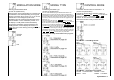
18 Set-Up Menu
General notes
You have concluded the basic programming of the
transmitter. If no special functions, like servo travel
adjustment, servo reversal, mixer and coupling
function etc., are necessary, you can now already
put your model into operation. Look up the basic
outline of the multi-function finished programs on
page 26 and 27, or test them using the detailed
descriptions for the model type used.
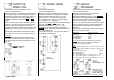
Model Type See page
Standard (FL) 28
Unifly (UN) 34
F3B/Butterfly (Fb) 42
Aerobatic (AC) 52
Helicopter (HE) 62
The modelling beginner is recommended to choose
models with control over rudders and elevators, and
if necessary also over Ailerons. Select the standard
model type "FL" in the system menu.
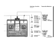
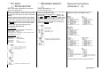
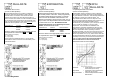
Flow charts and block diagrams
Those the individual sections placed in front
flowcharts
contain the available in each case codes.
(see page 19).
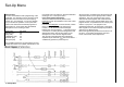
From the block diagrams
it can be inferred, in which
place in the signal flow from the signal of the
controls, i.e. can be influenced and changed
between the control functions 1 – 8 and the receiver
connections. For clarity the same designations and
abbreviations were used as with respect to the
descriptions of code. See the diagram below.
The controls at the transmitter are symbolically
explained by the character
. The control sticks 1 –
4 additionally possess a (electronic) trim.
Since these are not influenced by the dual rate and
exponential function, their signal process is drawn
separately. The cross connections show, which
channels are linked together with certain finished
programs. For the freely programmable mixers, see
page 22 and 23, of importance are the "output point"
and the " input point ". The program in the
appropriate place tests, at which point in the signal
flow a signal is to be measured (outputs) and which
channel it is to affect (inputs).
Before the signal finally arrives at the receiver or at
the servo, it can still be influenced by the servo
travel, reversal and neutral adjustment.