
Operation Manual


Compatibility of Computer Systems Basics
mc-16/20
12 General Section
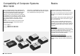
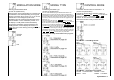
The mc-16/20 transmitter can be operated with all
currently available Graupner FM PPM receivers, as
well as other receivers with negative going pulses,
from the 35 and 40 MHz frequency band. Slight
reduction of servo travel can become countered by
the transmitter up to a maximum of ±160%. Also the
neutral position of servos attached receiver channels
1 to 8 can be adapted in ±125 steps, which is
approximately ±70% of normal travel, for all 8
Servos.
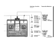
In the mc-16/20 Transmitter an FM quartz crystal
(black plastic cap) with corresponding channel
number must be used.
Part No. 3864, or
3264 for the 35 MHz band
Part No. 4064 for the 40 MHz band
Alternatively, the GRUNDIG receiver can be used,
but it is to be made certain that these are equipped
with a GRUNDIG FM quartz (green tab).
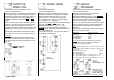
A protective plastic film is attached to the input
keyboard of the transmitter, and can be taken off.
Only switch on transmitter with the aerial screwed in,
otherwise it may malfunction and damage the HF
module.
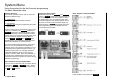
The allocation of the receiver outlets depends on the
type of model selected, and is described on pages
28, 34, 42, 52 and 62.
In order to avoid uncontrolled movements of the
servos attached to receiver outlets, first switch the
transmitter on, then switch on the receiver. After the
relevant operations switch off the receiver, then the
transmitter.
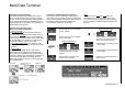
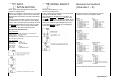
Range Check
With a new model a range test on the ground, with
the transmitter antenna screwed in but not extended,
should be completed before the first flight. The
model should be tested with the engine running and
if available check the fail-safe operation.
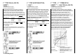
Adjustment of the transmitter aerial
In the direction of the extension of the transmitter
antenna, only a small field strength is formed. It is
therefore wrong to point the antenna directly at the
model.