
User manual


95
Program description: helicopter mixers – model helicopter
the right-hand four-way button (CLEAR) resets an al-
tered value to the default value.
Press the central 5. SET button of the right-hand four-
wa
y button to conclude the input process.
ptch (Collective pitch (ch1 ¼ pitch))
Select the “Collective pitch” line using the arrow buttons
cd of the left or right-hand four-way button, then press
the central SET button of the right-hand four-way button:
input
output
point
3
0%
0%
0%
ptch
normal
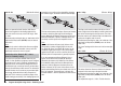
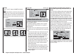
The control curve can be based on a maximum of
fi
ve nodes, known as “reference points”, which can be
placed along the length of the control travel; separate
curves can be programmed for each fl ight phase.
However, in most cases it is suffi cient to use a smaller
number of reference points when defi ning the collective
pitch curve. As a basic rule we recommend that you
start with the three default reference points offered by
the software. These three points, i. e. the two end-points
“Point 1” (collective pitch minimum) and “Point 5” (collec-
tive pitch maximum), and “Point 3”, exactly in the centre
of the travel, initially describe a linear characteristic
for the collective pitch curve; this is represented in the
picture above.
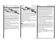
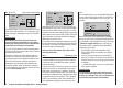
The programming procedure in detail
The throttle / collective pitch stick can now be used to
move the vertical line in the graph between the two
end-points “Point 1” and “Point 5”; at the same time the
momentary position of the stick is displayed in numeric
form in the “Input” line (-100% to +100%).
The point where the vertical line crosses the curve is
termed the “Output”, and this point can be varied within
the range -125% and +125% at a maximum of fi ve
reference points. The control signal, modifi ed in this way,
affects the collective pitch servos only. In the picture on
the left the stick is exactly at the 0% position at “Point
3”, and also generates an output signal of 0% due to the
linear nature of the graph.
By default only points “1” (collective pitch minimum at
-100%), “3” (hover point at 0%) and “5” (collective pitch
maximum at +100% travel) are active.
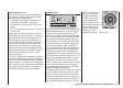
To set a point you use the associated stick to move the
vertical line to the point you wish to change. The number
and current curve value of this point are displayed in
the bottom line in the left-hand half of the screen in the
“Point” line. The arrow buttons of the right-hand four-way
button can now be used to change the current curve
value in the highlighted fi eld to any value within the
range -125% to +125%, without affecting the adjacent
points.
input
output
point
3
0%
+75%
+75%
ptch
normal
In this example we have moved reference point “3” to
+75%.
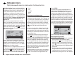
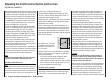
However, the optional points “2” and “4” can also be
activated. In the next example we activate point “2” at
-50% …
input
output
point
2
–50%
–12%
deact
ptch
normal
… and point “4” at +50% …
input
output
point 4
+50%
+88%
deact
ptch
normal
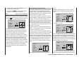
This is accomplished using the stick to move the vertical
line to the appropriate area. As soon as the message
“inactive” appears in the highlighted value fi eld, you can
activate the associated point with the arrow buttons of
the right-hand four-way button; it can then be adjusted in
the same manner as the other points …
input
output
point 4
+50%
–50%
–50%
ptch
normal
… or reset to “inactive” by simultaneously pressing the
cd or ef buttons of the right-hand four-way button