
User manual


69
Program description: base settings - model helicopter
With this in mind, you may wish to alter the default •
fl ight phase name “Hover” for fl ight phase 2 to take
the inherent priorities into account; see below.
At the servo end the transition does not occur •
“abruptly”, but with a fi xed transition period of about
one second.
Programming
When you select “Phase 2” using the arrow buttons cd
of the left or right-hand four-way button, the “Name” fi eld
for that fl ight phase is already framed.
If the default name does not seem appropriate, press
the central SET button of the right-hand four-way button,
and the current setting is sho
wn highlighted.
Now use
the arrow buttons of the right-hand four-way button to
select an appropriate name from those available. Press
the SET button to conclude the input process.
Now press the f button of the left or right-hand four-
way button to move to the right-hand column, at the
bottom of the screen indicated by the switch symbol
, and press the central SET button. You can now assign
a switch to the phase as described on page 39.
For more information on fl ight phase programming
please refer to page 94, in the section entitled “Flight
phase specifi c settings for collective pitch, throttle and
tail rotor”.
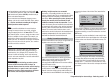
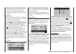
Auto-rotation
10:01 G3
phase 2 hover
–––
pitch min
rear
timer
5
autorotat.
rotor direct right
S
S
S
S
1
2
3
4
1
2
3
4
output
S
5
5
output
output
output
output
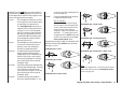
Use the arrow buttons cd of the left or right-hand f
our-
way button to select the servo / output combination you
wish to change, then press the central SET button of
the right-hand four-way button. Now you can assign the
desired servo (S) to the selected output using the right-
hand arrow buttons, and confi rm your choice with SET
… or alternatively press the cd or ef buttons of the
right-hand four-way button (CLEAR) simultaneously to
revert to the default sequence.
Please note that any subsequent changes to servo
settings, such as servo travel, Dual Rate / Expo, mixers
etc., must be carried out according to the original
(default) receiver socket sequence.
Typical application:
In the helicopter program of the mx-12 HoTT the
outputs for one collective pitch servo and the throttle
servo have been interchanged compared to all earlier
GRAUPNER/JR mc-systems. The throttle servo is now
assigned to receiver output “6” and the collective pitch
servo to output “1”. However, you may wish to retain the
earlier confi guration.
The name “Auto-rotation” is permanently assigned to
Phase 3, and CANNOT be altered. The only available
option is to assign a switch to it using the switch symbol
at the right of the screen.
For more information on programming fl ight phases
please refer to the “Helicopter mixers” section starting
on page 94.
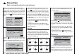
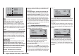
Receiver output
For maximum fl exibility in terms of receiver socket
assignment, the mx-12 HoTT software provides the
means to swap over the servo outputs 1 to max. 6;
this is carried out on the second page of the “Receiver
output” sub-menu.
10:01 G3
phase 2 hover
timer
5
autorotat.
4
receiv out
pitch min
rear
Press the central SET button of the right-hand four-way
button to move to the next page of the display. Here you
can assign the transmitter’s six “control channels” to
any receiver output you wish to use, i. e. servo sockets
1 … 6. However, please note that the display in “Servo
display” - which you can access from virtually any
menu position by simultaneously pressing the e and f
buttons of the left-hand four-way button - refers exclu-
sively to the “control channels”, i. e. the outputs are NOT
swapped over.