
User manual


107
Program description: free mixers
Note:
If you have selected the supplementary control func-
tions, don’t forget to assign transmitter controls to the
selected control functions 5 and / or 6 for a fi xed-wing
model, or 5 for a model helicopter, in the “Transmitter
control settings” menu.
“S” for switch channel
The letter “S” (switch channel) in the “from” column has
the effect of passing a constant input signal to the mixer
input, e. g. in order to apply a little extra up-elevator trim
when an aero-tow coupling is closed, as mentioned
earlier.
Once you have assigned a control function or the letter
“S” in the “from” column, an additional …
“to”
… appears at the bottom edge of the screen.
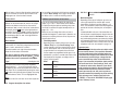
In the input fi eld of this column you can defi ne the
control channel as the mixer destination, i. e. the mixer
output. At the same time additional fi elds appear at the
bottom line of the screen:
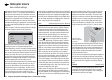
typ fro
to
M1
M2
M3
c1
el
c1
6
el
el
S3
5
In this example three mixers have already been defi ned.
The second mixer (“Brake ¼ el”) is already familiar to
us from the “Fixed-wing mixers” menu. As a general
rule you should always start by using these pre-pro-
grammed mixers if possible.
However, if you need asymmetrical mixer ratios on both
Regardless of the selected model type, three linear mix-
ers are available for each of the ten model memories,
with the additional possibility of setting up non-linear
characteristic curves.
In this fi rst section we will concentrate on the program-
ming procedure for the fi rst screen page. We will then
move on to the method of programming mixer ratios, as
found on the second screen page of this menu.
The basic programming procedure
Use the arrow buttons 1. cd of the left or right-hand
four-way button to select the desired mixer.
Press the central 2. SET button of the right-hand four-
w
a
y button: the input fi eld in the column marked
“fro(m)” at the bottom edge of the screen is now high-
lighted (black background).
Use the arrow buttons of the right-hand four-way but-3.
ton to defi ne the mixer input “fro(m)”.
Press the central 4. SET button of the right-hand four-
w
a
y button; switch to the “to” column using the f
button of the left or right-hand four-way button, then
press the central SET button of the right-hand four-
way button once more: the input fi eld “to” is now high-
lighted.
Use the arrow buttons of the right-hand four-way but-5.
ton to defi ne the mixer input “to”.
Press the central 6. SET button of the right-hand four-
w
a
y button, and (optionally) use the e button of the
left or right-hand four-way button to move to the col-
umn marked “Type” at the bottom edge of the screen;
you can now include the Ch1 … Ch 4 trim lever for
the mixer input signal (“Tr” for trim) …
… and / or use the 7. f arrow button of the left or right-
hand four-way button to move to the column marked
Free mixers
Linear mixers
with the switch symbol at the bottom edge of
the screen, press the central SET button of the right-
hand four-way button again, and assign a switch if
desired, as described on page 39.
Use the arrow button8. f of the left or right-hand four-
way button to move to the => column, then press the
central SET button of the right-hand four-way button.
Defi
ne the mixer ratios on the second screen page.9.
Press the central 10. ESC button of the left-hand four-
w
a
y button to switch back to the fi rst page.
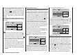
“fro(m)”
After briefl y pressing the central SET button of the right-
hand four-w
ay button, select the highlighted fi eld of the
selected mixer line using the arrow buttons of the same
four-way button, and select one of the control functions
1 … 6 or S.
In the interests of clarity, the control functions 1 … 4 are
abbreviated as follows when dealing with the fi xed-wing
mixers:
c1 Throttle / airbrake stick
ar Aileron stick
el Elevator stick
rd Rudder stick
… and in the Heli program:
1 Throttle / collective pitch stick
2 Roll stick
3 Pitch-axis stick
4 Tail rotor stick