
User's Manual


41 / 48
S1008_X-8E_jh_V1
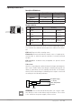
Operating receiver GR-8
Description LED indicator
Red LED Green LED
Not bound Flashing Off
Bound Off On
Error Flashing On
Binding Flashing Flashing
Channels function
Function Alternative
CH 1 Channel 1 signal
output
SUMD-V2 BUS system Battery plug
connection
CH 2 Channel 2 signal
output
SUMD-V2 BUS system Battery plug
connection
CH 3 Channel 3 signal
output
SUMD-V2 BUS system Battery plug
connection
CH 4 Channel 4 signal
output
SUMD-V2 BUS system Battery plug
connection
T/V Ext. temp./voltage
sensor
------
The power source for the receiver is connected through channel
1 to 4. If all of the channels are used, use a Y-cable on one chan-
nel.
CH 1+2: Connected the steering servo.
Channel 2: Connected with the throttle servo of engine-pow-
ered models or with the speed controller of electric-powered
models.
CH 3+4: Open channels freely assignable for special control
functions.
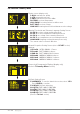
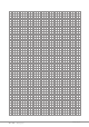
T/V socket:
Used to connecting the optional external voltage and tempera-
ture sensor S8362. When reaching the warning thresholds, an
alarm is generated (set the warning thresholds via Telemetry
menu). Sensor and voltage of a battery must only be connected
according to the following scheme:
ATTENTION: The receiver will be destroyed if you connect a bat-
tery directly to this socket without a pre-resistance. This socket
is not suited for the power supply of the receiver.
T
V
G
G
10K/C
NTC Temperatur-
Sensor
Ext.Spannung(+
)
(1 - 25,5V)
<CH3
<CH2
<CH1
<CH4
<T/V