OPERATING INSTRUCTION Prior to use, please read this manual thoroughly. Keep this manual in a convenient place for quick and easy reference.
GR-4 HoTT 2.
BOX CONTENTS GR-4 HoTT Receiver Manual Warranty Card Temperature/Voltage Sensor (S8362) WARNING NOTES • Never operate your car or truck in a crowded street with traffic. Especially, do not drive in a place near railway, chemical substance, gas to prevent any damage. • This product is not intended for use by inexperienced or disabled person without direct supervision of a responsible, knowledgeable adult. This is not suitable for children under 18 years.
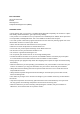
Binding & RF Range Test BIND Press and hold Bind button for 3 sec while your receiver is powered on and then LED indicator is off. Now press Bind button of your transmitter and then receiver’s LED indicator is off. Binding Button Binding Button Control Button RF RANGE TEST When BIND button is touched after the connection between transmitter and receiver, RF RANGE TEST is now activated. RF TEST is continued during 90 seconds and it is automatically deactivated.
Receiver Specification and Port Description 1. GR-4 Receiver Specification Channel Frequencies Modulation Input Voltage Output Power Operating Current Display Indicator 2CH 2400 – 2483.5Mhz FHSS 3.6 ~ 8.4V 60mW 35mA One LED(red) Extra Function Yes(Port3) Fail Safe free/Fail safe External Temp Sensor Port4(10 ~ 200`C) External Voltage Sensor Telemetry Sensor Port4(1.0 ~ 25.5V) Port3 Size 30x21x14.3 mm (1.18x0.82x0.56 in) Weight 5.5 g ( 0.19 oz) 2.
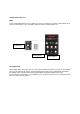
1) Port 1, 2 should be connected to servo or ESC. 2) Port 3 supports low voltage warning alarm with beep and LED indicator. In addition, it is available to use with telemetry sensor. When using receiver battery (Nixx 4~5 cell, LiPo 2 cell), it needs to be connected to Port3. As for low voltage warning alarm, the default value is 3.7V.
LED and Buzzer indication RX BIND ON RX BIND OFF Rang TEST Fail Safe Setup/Cancel Free Warning Status Tx Receive Rate Low Sensor Warning Rx Ex Temp High Rx Ex Volt Low Rx Voltage Low Tx Low Battery Bind Switch Push Push (Bind on status) RED GREEN ON Slow flash ON Slow flash Push 3sec (Bind on status) ON 3 blink Low 3Time ON 2 blink Low 2Time 1cycle 2cycle 3cycle 4cycle 5cycle 6cycle - 1cycle 2cycle 3cycle 4cycle 5cycle 6cycle - Buzzer Low 2Time(90sec)
COMPLIANCE INFORMATION FOR THE EUROPEAN UNION
• NOTE This equipment has been tested and found to comply with the limits for a Class B digital device, pursuant to Part 15 of the FCC Rules. These limits are designed to provide reasonable protection against harmful interference in a residential installation. This equipment generates uses and can radiate radio frequency energy and, if not installed and used in accordance with the instructions, may cause harmful interference to radio communications.