
Installation Guide

12
13
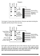
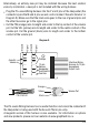
Diagram 8.
Acousti-Phonic
Pass-Through
Connector
Pickup
Connector
Interface Wiring
Harness
13-Pin
Hexaphonic
Output Jack
Panel
Connector
Control
Connector
Acousti-Phonic
Connector
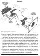
Wire the Hexpander as follows:
Plug the Interface Wiring Harness cable onto the Panel connector of the
Hexpander. This makes all the connections from Hexpander to 13 -pin Output
Jack at once. The Harness must be oriented as shown in Diagram 8 above.
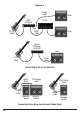
Plug the wires from the pickups onto the Pickup Connector of the Hexpander.
The pickups must be connected in the right order otherwise the external MIDI
converter or sound processor will not relay information correctly. If you did not
use the Extension Harness, plug the pickup wires on to pins 1 through 6 on the
Hexpander. The slots are numbered 1 (highest note) to 6 (lowest note). The blue
tracer wire from each saddle must connect to the Ground side of the connector
pins.
If you used the Extension Harness, plug it on to the connector. This makes all
connections at once. The blue tracer wire comes from pickup Number 1 and
should connect to the ground side of the Number 1 connector pin.
•
•
•