
Installation Guide

10
11
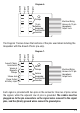
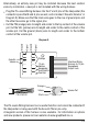
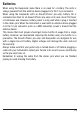
Pickups
Function
13-pin
Volume
Interface Wiring
Harness to 13-pin
Hexaphonic
Output Jack
Diagram 6.
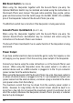
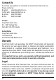
The Diagram 7 below shows the functions of the pins used when installing the
Hexpander with the Acousti-Phonic pre-amp.
Diagram 7.
GHOST
Pickups
Function
Hexpander
QuickSwitch
Volume
Interface Wiring
Harness to 13-pin
Hexaphonic
Output Jack
Volume &
Magnetic
Pickups
Acousti-Phonic
QuickSwitch
Stereo Jack
Power Output
& Battery Input
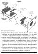
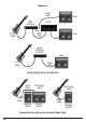
Each signal is provided with two pins on the connector. One row of pins carries
the signals, while the adjacent row of pins is grounded. The cables must be
plugged on to the pin connectors so the signal wires connect to the signal
pins, and the (black) ground wires connect to ground pins.
Ground
Signal
Ground
Signal
Ground
Signal
Ground
Signal
Hexpander
QuickSwitch