
Installation Guide


10
11
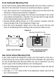
Drill a 5/8 inch clearance hole for the 13-pin Hexpander Output Jack from
the front of the instrument through to the new cavity. Drill two small holes for
mounting screws (Diagram 5).
Cut or drill a connecting passage from the Hexpander Output Jack cavity
through to the control cavity where the Hexpander is mounted. This passage
must be large enough for the Interface Wiring Harness (BE-0512-00).
Plug the Interface Wiring Harness on to the 13-pin Hexpander Output Jack.
Feed the Harness through to the control cavity.
Place the 13-pin Hexpander Output Jack in the new cavity. Secure in place
with two machine screws, lock washers and nuts.
•
•
•
•
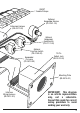
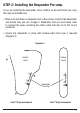
Wherever you install the 13-pin Hexpander Output Jack, position it so that your
13-pin cable will not be in the way when playing, or when you set the instrument
down or place it on a stand.
Output Jack Hole Size Output Jack Rear Installation
Diagram 5.
7/8”
1/16”
5/8”
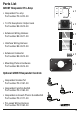
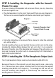
STEP 5: Wiring the Hexpander Pre-Amp
Connections to the Hexpander are made via the connectors on top of the board.
The supplied cable assemblies plug on to these connectors, making installation
easy.
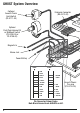
Diagram 6 shows the functions of the pins used when installing the Hexpander
alone.
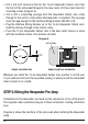
Guitar Body