Plug into a world of possibilities.
Welcome to a World of Possibilities! Congratulations on your purchase of the GHOST™ Hexpander System! Using the highest quality components and state of the art design, the Ghost Hexpander System perfectly complements the latest midi, hexaphonic and/or virtual devices. Experience fast and accurate tracking that absolutely smokes... without volume dropouts or dead spots! The Ghost Hexpander System is your gateway to the infinite world of hexaphonic, virtual and midi possibilities.
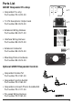
Parts List GHOST Hexpander Pre-Amp • Hexpander Pre-amp Part number PE-0410-00 x1 • 13-Pin Hexaphonic Output Jack Part number BE-0510-00 x1 • Extension Wiring Harness Part number BE-0511-00 x1 • Interface Wiring Harness Part number BE-0512-00 x1 • Extension Connector Part number BE-0513-00 x1 • Mounting Plate & Hardware Part number BE-0514-00 x1 Optional GHOST Hexpander Controls • Hexpander Volume Pot Part number PE-0181-00 • Hexpander Function Switch Part number PE-0180-00 • Hexpander & Acousti
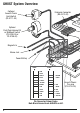
GHOST System Overview Optional Acousti-Phonic QuickSwitch (PE-0111-00) Extension Connector (BE-0513-00) Optional Push/Push Volume Pot or MidBoost Switch (PE-0206-00 or PE-0106-00) Magnetic In Stereo Jack Power/Battery BLACK BLACK Q RED 1 Q BLUE 2 P EMPTY 3 M BLUE 4 G PURPLE 5 V YELLOW 6 M GREEN VO RED R RED VI T BLUE MM RED S WHITE AM BLUE P RED S1 PURPLE B RED S2 YELLOW RIBBON CABLE WHITE Pin Connector Colour Codes. Note Black Ground leads ALWAYS on left.
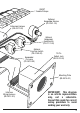
GHOST Saddle Pickups Optional Hexpander Volume (PE-0181-00) Extension Harness (BE-0511-00) Optional Hexpander QuickSwitch (PE-0111-00) Optional Function Switch (PE-0180-00) Hexpander Pre-amp (PE-0410-00) 13-Pin Output Jack (BE-0510-00) Mounting Plate (BE-0514-00) Interface Wiring Harness (BE-0512-00) IMPORTANT! This diagram is an artistic representation only, not a schematic. Consult this guide for correct wiring procedure to avoid voiding your warranty.
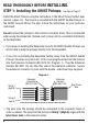
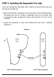
READ THOROUGHLY BEFORE INSTALLING. STEP 1: Installing the GHOST Pickups. See tips on Page 21. Install the Ghost Pickups using the instructions in the Ghost Pickup System user manual, pages 4-6. The manual is included with the GHOST Saddle Pickups, or the GHOST Acousti-Phonic Pre-amp. Follow the instructions for your particular instrument. Do not connect the pickups to the common connector block. This is not needed when using the Hexpander.
STEP 2: Installing the Hexpander Pre-amp. If you are installing the Hexpander alone, without an Acousti-Phonic pre-amp, this may be installed now. • Make sure that there is adequate room in the control cavity for the Hexpander, and decide how you will arrange it. Remember that you must leave room to connect the wires, including the ribbon cable that will run to the 13-pin connector. • Secure the Hexpander in place with double-sided foam tape if required (Diagram 2). Diagram 2.
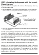
STEP 3: Installing the Hexpander with the AcoustiPhonic Pre-amp If you are installing the Hexpander with an Acousti-Phonic pre-amp, these may be installed together now. • Plug the Hexpander on to the top of the Acousti-Phonic pre-amp (Diagram 3). The two can be secured together with double-sided foam tape if required. Diagram 3. Hexpander Pre-amp Hexpander Plugged on Top of Acousti-Phonic Pre-amp.
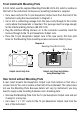
Front Install with Mounting Plate A front install uses the supplied Mounting Plate (BE-0514-00), which is visible on the front of the instrument. All necessary mounting hardware is supplied. • Cut a new cavity for the 13-pin Hexaphonic Output Jack from the front of the instrument, using the measurements in Diagram 4. • Cut or drill a connecting passage from the new cavity through to the control cavity where the Hexpander is mounted.
• Drill a 5/8 inch clearance hole for the 13-pin Hexpander Output Jack from the front of the instrument through to the new cavity. Drill two small holes for mounting screws (Diagram 5). • Cut or drill a connecting passage from the Hexpander Output Jack cavity through to the control cavity where the Hexpander is mounted. This passage must be large enough for the Interface Wiring Harness (BE-0512-00). • Plug the Interface Wiring Harness on to the 13-pin Hexpander Output Jack.
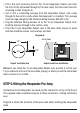
Signal Ground Signal Ground Diagram 6. Pickups 13-pin Volume Hexpander QuickSwitch Function Interface Wiring Harness to 13-pin Hexaphonic Output Jack The Diagram 7 below shows the functions of the pins used when installing the Hexpander with the Acousti-Phonic pre-amp. Acousti-Phonic QuickSwitch Volume & Magnetic Pickups Stereo Jack Power Output & Battery Input Signal Ground Signal Ground Diagram 7.
Diagram 8. Acousti-Phonic Pass-Through Connector Pickup Connector Interface Wiring Harness 13-Pin Hexaphonic Output Jack Acousti-Phonic Connector Control Connector Panel Connector Wire the Hexpander as follows: • Plug the Interface Wiring Harness cable onto the Panel connector of the Hexpander. This makes all the connections from Hexpander to 13 -pin Output Jack at once. The Harness must be oriented as shown in Diagram 8 above.
That’s it! If you are installing the Hexpander with the Acousti-Phonic pre-amp proceed with the next section. If you are installing any of the optional Hexpander controls see the following sections. Step 6: Wiring the Acousti-Phonic Pre-Amp (PE-0210-00) If you are installing the Hexpander with the Acousti-Phonic pre-amp you can wire the Acousti-Phonic connectors and controls exactly as shown in the AcoustiPhonic manual.
processed sound only, analog sound only, or both. This selector switch only affects the analog signal on the 13-pin Hexpander Output Jack. It has no effect on the analog signals that the Acousti-Phonic pre-amp sends to the stereo jack. You can omit this switch if you don’t need it. • Plug the cable assembly from the Hexpander QuickSwitch into the MM and AM pins of the Hexpander (marked “Hexpander QuickSwitch” in Diagram 7).
Alternatively, an entirely new pot may be installed. Because the best solution varies by installation, a new pot is not included with the wiring harness. • Plug the Pin-seven Wiring Harness into the P and V pins of the Hexpander (the connector spans the M and G pins as well, and is marked “Acoustic Volume” in Diagram 9). Make sure that the black wire goes to the row of ground pins and the other two wires go to the signal pins.
Mid Boost Switch (PE-0106-00) When using the Hexpander together with the Acousti-Phonic pre-amp, the Optional Mid/Dark Switch may be installed and wired using the instructions in the Acousti-Phonic user manual. The quad cable assembly (blue, purple, yellow, green and black wires) from the switch plugs into the MID, GHOST, VOL and MAG pins of the Hexpander instead of the Acousti-Phonic pre-amp. The Mid/Dark switch has no function if the Hexpander is being used alone.
Step 8: Setup Set up your action and intonation using the instructions in the Ghost Pickup user manual. Read through the instructions one more time and make sure everything is connected up correctly. Make sure that there are no loose wires, wire “whiskers” or metal filings that might make a short circuit. Connect the 13-pin socket via a 13-pin cable to a MIDI converter, sound processor or other 13-pin compatible device.
Diagram 9. Audio Cable MIDI Converter Amp Synth MIDI Cable 13-Pin Cable Amp Sound Processor i.e.
Batteries When using the Hexpander alone there is no need for a battery. The units is always powered from the external device plugged in to the 13-pin connector. When using the Hexpander with an Acousti-Phonic pre-amp, battery life is somewhat less than for an Acousti-Phonic pre-amp on its own; about 150 hours of continuous use. However, battery power is only used when a plug is inserted in the stereo jack.
Contact Us If you have any questions or comments we would love to hear from you. Please contact us: By email: sales@graphtech.bc.ca On the web: www.graphtech.bc.ca By phone: (604) 940-5353 By fax: (604) 940-4961 Canada Graph Tech Guitar Labs #5 - 7551 Vantage Way, Delta, BC V4G 1C9 Canada United States Graph Tech Guitar Labs 145 Tyee Drive, Point Roberts, WA 98281 U.S.A.
Installation Tips • Many guitar cavities are coated with either electrically conductive paints or foil tapes to help isolate the circuitry from interference. When installing the Acousti-Phonic Intelligent Pre-amp it is very important to make sure that the pre-amp is completely isolated from this electrically conductive material. • Do not attempt to install the pre-amp by using screws through the two holes in the pre-amp, as they are there only for manufacturing purposes.
Potentiometer (Pot) Contact Key Top Contact Center Contact Bottom Contact 22 Diagram 14.
Notes 23